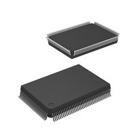
HD64F2636UF20 Renesas Electronics America, HD64F2636UF20 Datasheet - Page 41

HD64F2636UF20
Manufacturer Part Number
HD64F2636UF20
Description
IC H8S MCU FLASH 128K 128QFP
Manufacturer
Renesas Electronics America
Series
H8® H8S/2600r
Specifications of HD64F2636UF20
Core Processor
H8S/2600
Core Size
16-Bit
Speed
20MHz
Connectivity
CAN, SCI, SmartCard
Peripherals
Motor Control PWM, POR, PWM, WDT
Number Of I /o
72
Program Memory Size
128KB (128K x 8)
Program Memory Type
FLASH
Ram Size
4K x 8
Voltage - Supply (vcc/vdd)
4.5 V ~ 5.5 V
Data Converters
A/D 12x10b; D/A 2x8b
Oscillator Type
Internal
Operating Temperature
-20°C ~ 75°C
Package / Case
128-QFP
Lead Free Status / RoHS Status
Contains lead / RoHS non-compliant
Eeprom Size
-
- Current page: 41 of 1512
- Download datasheet (9Mb)
17.3 Interface to Bus Master ..................................................................................................... 691
17.4 Operation .......................................................................................................................... 692
17.5 Interrupts ........................................................................................................................... 698
17.6 Usage Notes ...................................................................................................................... 699
Section 18 D/A Converter
18.1 Overview........................................................................................................................... 705
18.2 Register Descriptions ........................................................................................................ 708
18.3 Operation .......................................................................................................................... 711
Section 19 Motor Control PWM Timer
19.1 Overview........................................................................................................................... 713
19.2 Register Descriptions ........................................................................................................ 718
19.3 Bus Master Interface ......................................................................................................... 731
REJ09B0103-0800 Rev. 8.00
May 28, 2010
17.4.1 Single Mode (SCAN = 0) .................................................................................... 692
17.4.2 Scan Mode (SCAN = 1)....................................................................................... 694
17.4.3 Input Sampling and A/D Conversion Time ......................................................... 696
17.4.4 External Trigger Input Timing............................................................................. 697
18.1.1 Features................................................................................................................ 705
18.1.2 Block Diagram..................................................................................................... 706
18.1.3 Input and Output Pins .......................................................................................... 707
18.1.4 Register Configuration......................................................................................... 707
18.2.1 D/A Data Registers 0, 1 (DADR0, DADR1) ....................................................... 708
18.2.2 D/A Control Register 01 (DACR01) ................................................................... 708
18.2.3 Module Stop Control Register A (MSTPCRA) ................................................... 710
19.1.1 Features................................................................................................................ 713
19.1.2 Block Diagram..................................................................................................... 714
19.1.3 Pin Configuration................................................................................................. 716
19.1.4 Register Configuration......................................................................................... 717
19.2.1 PWM Control Registers 1 and 2 (PWCR1, PWCR2) .......................................... 718
19.2.2 PWM Output Control Registers 1 and 2 (PWOCR1, PWOCR2) ........................ 720
19.2.3 PWM Polarity Registers 1 and 2 (PWPR1, PWPR2)........................................... 721
19.2.4 PWM Counters 1 and 2 (PWCNT1, PWCNT2) .................................................. 722
19.2.5 PWM Cycle Registers 1 and 2 (PWCYR1, PWCYR2) ....................................... 723
19.2.6 PWM Duty Registers 1A, 1C, 1E, 1G (PWDTR1A, 1C, 1E, 1G) ....................... 724
19.2.7 PWM Buffer Registers 1A, 1C, 1E, 1G (PWBFR1A, 1C, 1E, 1G) ..................... 726
19.2.8 PWM Duty Registers 2A to 2H (PWDTR2A to PWDTR2H) ............................. 727
19.2.9 PWM Buffer Registers 2A to 2D (PWBFR2A to PWBFR2D)............................ 729
19.2.10 Module Stop Control Register D (MSTPCRD) ................................................... 730
19.3.1 16-Bit Data Registers........................................................................................... 731
................................................................................................. 705
........................................................................ 713
Page xli of l
Related parts for HD64F2636UF20
Image
Part Number
Description
Manufacturer
Datasheet
Request
R

Part Number:
Description:
KIT STARTER FOR M16C/29
Manufacturer:
Renesas Electronics America
Datasheet:

Part Number:
Description:
KIT STARTER FOR R8C/2D
Manufacturer:
Renesas Electronics America
Datasheet:

Part Number:
Description:
R0K33062P STARTER KIT
Manufacturer:
Renesas Electronics America
Datasheet:

Part Number:
Description:
KIT STARTER FOR R8C/23 E8A
Manufacturer:
Renesas Electronics America
Datasheet:

Part Number:
Description:
KIT STARTER FOR R8C/25
Manufacturer:
Renesas Electronics America
Datasheet:

Part Number:
Description:
KIT STARTER H8S2456 SHARPE DSPLY
Manufacturer:
Renesas Electronics America
Datasheet:

Part Number:
Description:
KIT STARTER FOR R8C38C
Manufacturer:
Renesas Electronics America
Datasheet:

Part Number:
Description:
KIT STARTER FOR R8C35C
Manufacturer:
Renesas Electronics America
Datasheet:

Part Number:
Description:
KIT STARTER FOR R8CL3AC+LCD APPS
Manufacturer:
Renesas Electronics America
Datasheet:

Part Number:
Description:
KIT STARTER FOR RX610
Manufacturer:
Renesas Electronics America
Datasheet:

Part Number:
Description:
KIT STARTER FOR R32C/118
Manufacturer:
Renesas Electronics America
Datasheet:

Part Number:
Description:
KIT DEV RSK-R8C/26-29
Manufacturer:
Renesas Electronics America
Datasheet:

Part Number:
Description:
KIT STARTER FOR SH7124
Manufacturer:
Renesas Electronics America
Datasheet:

Part Number:
Description:
KIT STARTER FOR H8SX/1622
Manufacturer:
Renesas Electronics America
Datasheet:


