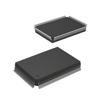
HD64F2636UF20 Renesas Electronics America, HD64F2636UF20 Datasheet - Page 481

HD64F2636UF20
Manufacturer Part Number
HD64F2636UF20
Description
IC H8S MCU FLASH 128K 128QFP
Manufacturer
Renesas Electronics America
Series
H8® H8S/2600r
Specifications of HD64F2636UF20
Core Processor
H8S/2600
Core Size
16-Bit
Speed
20MHz
Connectivity
CAN, SCI, SmartCard
Peripherals
Motor Control PWM, POR, PWM, WDT
Number Of I /o
72
Program Memory Size
128KB (128K x 8)
Program Memory Type
FLASH
Ram Size
4K x 8
Voltage - Supply (vcc/vdd)
4.5 V ~ 5.5 V
Data Converters
A/D 12x10b; D/A 2x8b
Oscillator Type
Internal
Operating Temperature
-20°C ~ 75°C
Package / Case
128-QFP
Lead Free Status / RoHS Status
Contains lead / RoHS non-compliant
Eeprom Size
-
- Current page: 481 of 1512
- Download datasheet (9Mb)
H8S/2639, H8S/2638, H8S/2636,
H8S/2630, H8S/2635 Group
Bit 7—Overflow Flag (OVF): Indicates that TCNT has overflowed from H'FF to H'00.
Bit 7
OVF
0
1
Note: * When interval timer interrupts are disabled and OVF is polled, read the OVF = 1 state at
In the interval timer mode, the OVF flag can be cleared in the interval timer interrupt routine by
writing 0 to OVF after reading TCSR when OVF is set to 1, in accordance with the conditions for
clearing the OVF flag.
However, when attempting to poll the OVF flag when interval timer interrupts are prohibited the
OVF value will not be recognized as 1 (even though it is set to 1) if there is a conflict between the
timing used to set the OVF flag and the timing used to read the OVF flag.
In such cases it is possible to completely satisfy the conditions for clearing the OVF flag by
reading OVF two or more times while its value is 1. In a situation such as the above, the OVF flag
should be read two or more times while its value is 1 and then cleared.
Bit 6—Timer Mode Select (WT/IT): Selects whether the WDT is used as a watchdog timer or
interval timer. This selection determines whether WDT0 issues an internal reset when TCNT
overflows while bit RSTE of the reset control/status register (RSTCSR) is set to 1. In the interval
timer mode, WDT0 sends a WOVI interrupt request to the CPU. WDT1, on the other hand,
requests a reset or an NMI interrupt from the CPU if the watchdog timer mode is chosen, whereas
it requests a WOVI interrupt from the CPU if the interval timer mode is chosen.
REJ09B0103-0800 Rev. 8.00
May 28, 2010
least twice.
Description
[Clearing conditions]
•
•
[Setting condition]
•
Cleared when 0 is written to the TME bit (Only applies to WDT1)
Cleared by reading TCSR * when OVF = 1, then writing 0 to OVF
When TCNT overflows (changes from H'FF to H'00)
When internal reset request generation is selected in watchdog timer mode, OVF is
cleared automatically by the internal reset.
Section 12 Watchdog Timer
Page 431 of 1458
(Initial value)
Related parts for HD64F2636UF20
Image
Part Number
Description
Manufacturer
Datasheet
Request
R

Part Number:
Description:
KIT STARTER FOR M16C/29
Manufacturer:
Renesas Electronics America
Datasheet:

Part Number:
Description:
KIT STARTER FOR R8C/2D
Manufacturer:
Renesas Electronics America
Datasheet:

Part Number:
Description:
R0K33062P STARTER KIT
Manufacturer:
Renesas Electronics America
Datasheet:

Part Number:
Description:
KIT STARTER FOR R8C/23 E8A
Manufacturer:
Renesas Electronics America
Datasheet:

Part Number:
Description:
KIT STARTER FOR R8C/25
Manufacturer:
Renesas Electronics America
Datasheet:

Part Number:
Description:
KIT STARTER H8S2456 SHARPE DSPLY
Manufacturer:
Renesas Electronics America
Datasheet:

Part Number:
Description:
KIT STARTER FOR R8C38C
Manufacturer:
Renesas Electronics America
Datasheet:

Part Number:
Description:
KIT STARTER FOR R8C35C
Manufacturer:
Renesas Electronics America
Datasheet:

Part Number:
Description:
KIT STARTER FOR R8CL3AC+LCD APPS
Manufacturer:
Renesas Electronics America
Datasheet:

Part Number:
Description:
KIT STARTER FOR RX610
Manufacturer:
Renesas Electronics America
Datasheet:

Part Number:
Description:
KIT STARTER FOR R32C/118
Manufacturer:
Renesas Electronics America
Datasheet:

Part Number:
Description:
KIT DEV RSK-R8C/26-29
Manufacturer:
Renesas Electronics America
Datasheet:

Part Number:
Description:
KIT STARTER FOR SH7124
Manufacturer:
Renesas Electronics America
Datasheet:

Part Number:
Description:
KIT STARTER FOR H8SX/1622
Manufacturer:
Renesas Electronics America
Datasheet:


