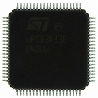
UPSD3433EB40U6 STMicroelectronics, UPSD3433EB40U6 Datasheet - Page 191

UPSD3433EB40U6
Manufacturer Part Number
UPSD3433EB40U6
Description
MCU 8BIT 8032 128KB FLASH 80TQFP
Manufacturer
STMicroelectronics
Series
µPSDr
Datasheet
1.UPSD3434EB40T6.pdf
(293 pages)
Specifications of UPSD3433EB40U6
Core Processor
8032
Core Size
8-Bit
Speed
40MHz
Connectivity
I²C, IrDA, SPI, UART/USART, USB
Peripherals
LVD, POR, PWM, WDT
Number Of I /o
46
Program Memory Size
160KB (160K x 8)
Program Memory Type
FLASH
Ram Size
8K x 8
Voltage - Supply (vcc/vdd)
3 V ~ 5.5 V
Data Converters
A/D 8x10b
Oscillator Type
Internal
Operating Temperature
-40°C ~ 85°C
Package / Case
80-TQFP, 80-VQFP
For Use With
497-5518 - EVAL BOARD RFID READER497-5046 - KIT TOOL FOR ST7/UPSD/STR7 MCU
Lead Free Status / RoHS Status
Lead free / RoHS Compliant
Eeprom Size
-
Other names
497-5660
Available stocks
Company
Part Number
Manufacturer
Quantity
Price
Company:
Part Number:
UPSD3433EB40U6
Manufacturer:
STMicroelectronics
Quantity:
10 000
- Current page: 191 of 293
- Download datasheet (5Mb)
uPSD34xx
28.1.16
28.1.17
28.2
Power management
The PSD Module has bits in csiop registers that are configured at run-time by the 8032 to
reduce power consumption of the GPLD. The Turbo Bit in the PMMR0 Register can be set to
logic ’1’ and both PLDs will go to Non-Turbo mode, meaning it will latch its outputs and go to
sleep until the next transition on its inputs. There is a slight penalty in PLD performance
(longer propagation delay), but significant power savings are realized. Going to Non-Turbo
mode may require an additional wait state in the 8032 SFR, BUSCON, because memory
decode signals are also delayed. The default state of the Turbo Bit is logic '0,' meaning by
default, the GPLD is in fast Turbo mode until the user turns off Turbo mode.
Additionally, bits in csiop registers PMMR0 and PMMR2 can be set by the 8032 to
selectively block signals from entering both PLDs which further reduces power
consumption. There is also an Automatic Power Down counter that detects lack of 8032
activity and reduces power consumption on the PSD Module to its lowest level (see
Section 28.1.16: Power management on page
Security and NVM Sector Protection
A programmable security bit in the PSD Module protects its contents from unauthorized
viewing and copying. The security bit is specified in PSDsoft Express and programmed into
the uPSD34xx with JTAG. Once set, the security bit will block access of JTAG programming
equipment to the PSD Module Flash memory and PLD configuration, and also blocks JTAG
debugging access to the MCU Module. The only way to defeat the security bit is to erase the
entire PSD Module using JTAG (the erase command is the only JTAG command allowed
after the security bit has been set), after which the device is blank and may be used again.
Additionally and independently, the contents of each individual Flash memory sector can be
write protected (sector protection) by configuration with PSDsoft Express. This is typically
used to protect 8032 boot code from being corrupted by inadvertent WRITEs to Flash
memory from the 8032.
Status of sector protection bits may be read (but not written) using two registers in csiop
space.
Memory mapping
There many different ways to place (or map) the address range of PSD Module memory and
I/O depending on system requirements. The DPLD provides complete mapping flexibility.
Figure 64
Flash memory for a uPSD3433 device is in 8032 program address space, and 32K bytes of
Secondary Flash memory, the SRAM, and csiop registers are all in 8032 XDATA space.
In
Flash memory, 16K bytes each. CSBOOT0..CSBOOT3 are designators for the individual
Secondary Flash memory segments, 8K bytes each. rs0 is the designator for SRAM, and
csiop designates the PSD Module control register set.
The designer may easily specify memory mapping in a point-and-click software environment
using PSDsoft Express, creating a non-volatile configuration when the DPLD is
programmed using JTAG.
Figure
64, the nomenclature fs0..fs7 are designators for the individual sectors of Main
shows one possible system memory map. In this example, 128K bytes of Main
191).
PSD module
191/293
Related parts for UPSD3433EB40U6
Image
Part Number
Description
Manufacturer
Datasheet
Request
R

Part Number:
Description:
MCU 8BIT 8032 128KB FLASH 80TQFP
Manufacturer:
STMicroelectronics
Datasheet:

Part Number:
Description:
MCU 8BIT 8032 128KB FLASH 52TQFP
Manufacturer:
STMicroelectronics
Datasheet:

Part Number:
Description:
STMicroelectronics [RIPPLE-CARRY BINARY COUNTER/DIVIDERS]
Manufacturer:
STMicroelectronics
Datasheet:

Part Number:
Description:
STMicroelectronics [LIQUID-CRYSTAL DISPLAY DRIVERS]
Manufacturer:
STMicroelectronics
Datasheet:

Part Number:
Description:
BOARD EVAL FOR MEMS SENSORS
Manufacturer:
STMicroelectronics
Datasheet:

Part Number:
Description:
NPN TRANSISTOR POWER MODULE
Manufacturer:
STMicroelectronics
Datasheet:

Part Number:
Description:
TURBOSWITCH ULTRA-FAST HIGH VOLTAGE DIODE
Manufacturer:
STMicroelectronics
Datasheet:

Part Number:
Description:
Manufacturer:
STMicroelectronics
Datasheet:

Part Number:
Description:
DIODE / SCR MODULE
Manufacturer:
STMicroelectronics
Datasheet:

Part Number:
Description:
DIODE / SCR MODULE
Manufacturer:
STMicroelectronics
Datasheet:

Part Number:
Description:
Search -----> STE16N100
Manufacturer:
STMicroelectronics
Datasheet:

Part Number:
Description:
Search ---> STE53NA50
Manufacturer:
STMicroelectronics
Datasheet:


