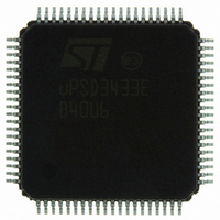
UPSD3433EB40U6 STMicroelectronics, UPSD3433EB40U6 Datasheet - Page 86

UPSD3433EB40U6
Manufacturer Part Number
UPSD3433EB40U6
Description
MCU 8BIT 8032 128KB FLASH 80TQFP
Manufacturer
STMicroelectronics
Series
µPSDr
Datasheet
1.UPSD3434EB40T6.pdf
(293 pages)
Specifications of UPSD3433EB40U6
Core Processor
8032
Core Size
8-Bit
Speed
40MHz
Connectivity
I²C, IrDA, SPI, UART/USART, USB
Peripherals
LVD, POR, PWM, WDT
Number Of I /o
46
Program Memory Size
160KB (160K x 8)
Program Memory Type
FLASH
Ram Size
8K x 8
Voltage - Supply (vcc/vdd)
3 V ~ 5.5 V
Data Converters
A/D 8x10b
Oscillator Type
Internal
Operating Temperature
-40°C ~ 85°C
Package / Case
80-TQFP, 80-VQFP
For Use With
497-5518 - EVAL BOARD RFID READER497-5046 - KIT TOOL FOR ST7/UPSD/STR7 MCU
Lead Free Status / RoHS Status
Lead free / RoHS Compliant
Eeprom Size
-
Other names
497-5660
Available stocks
Company
Part Number
Manufacturer
Quantity
Price
Company:
Part Number:
UPSD3433EB40U6
Manufacturer:
STMicroelectronics
Quantity:
10 000
- Current page: 86 of 293
- Download datasheet (5Mb)
Supervisory functions
19.5.1
86/293
In this example,
The actual value will be slightly longer due to PFQ/BC.
Firmware Example:
The following 8051 assembly code illustrates how to operate the WDT. A simple statement
in the reset initialization firmware enables the WDT, and then a periodic write to clear the
WDT in the main firmware is required to keep the WDT from overflowing. This firmware is
based on the example above (40MHz f
For example, in the reset initialization firmware (the function that executes after a jump to
the reset vector):
MOV AE, #AA
Somewhere in the flow of the main program, this statement will execute periodically to reset
the WDT before its time-out period of 1.67 seconds. For example:
MOV A6, #00
Table 39.
Table 40.
Bit 7
Bit 7
[7:0]
[7:0]
Bit
Bit
t
N
WDT
MACH_CYC
OVERFLOW
PERIOD
WDKEY: Watchdog timer key register (SFR AEh, reset value 55h)
WDRST: Watchdog timer reset counter register (SFR A6h, reset value
00h)
Symbol
WDKEY
Symbol
WDRST
Bit 6
Bit 6
= 100ns (4 MCU_CLK periods x 25ns)
= 2
= 100ns X 16777216 = 1.67 seconds
24
= 16777216 up-counts
Bit 5
Bit 5
R/W
R/W
W
W
; enable WDT by writing value to
; WDKEY other than 55h
; reset WDT, loading 000000h.
; Counting will automatically
; resume as long as 55h in not in
; WDKEY
55h disables the WDT from counting. 55h is automatically
loaded in this SFR after any reset condition, leaving the WDT
disabled by default.
Any value other than 55h written to this SFR will enable the
WDT, and counting begins.
This SFR is the upper byte of the 24-bit WDT up-counter.
Writing this SFR sets the upper byte of the counter to the
written value, and clears the lower two bytes of the counter to
0000h.
Counting begins when WDKEY does not contain 55h.
Bit 4
Bit 4
OSC
WDKEY[7:0]
WDRST[7:0]
, CCON0 = 10h, BUSCON = C1h).
Bit 3
Bit 3
Definition
Definition
Bit 2
Bit 2
Bit 1
Bit 1
uPSD34xx
Bit 0
Bit 0
Related parts for UPSD3433EB40U6
Image
Part Number
Description
Manufacturer
Datasheet
Request
R

Part Number:
Description:
MCU 8BIT 8032 128KB FLASH 80TQFP
Manufacturer:
STMicroelectronics
Datasheet:

Part Number:
Description:
MCU 8BIT 8032 128KB FLASH 52TQFP
Manufacturer:
STMicroelectronics
Datasheet:

Part Number:
Description:
STMicroelectronics [RIPPLE-CARRY BINARY COUNTER/DIVIDERS]
Manufacturer:
STMicroelectronics
Datasheet:

Part Number:
Description:
STMicroelectronics [LIQUID-CRYSTAL DISPLAY DRIVERS]
Manufacturer:
STMicroelectronics
Datasheet:

Part Number:
Description:
BOARD EVAL FOR MEMS SENSORS
Manufacturer:
STMicroelectronics
Datasheet:

Part Number:
Description:
NPN TRANSISTOR POWER MODULE
Manufacturer:
STMicroelectronics
Datasheet:

Part Number:
Description:
TURBOSWITCH ULTRA-FAST HIGH VOLTAGE DIODE
Manufacturer:
STMicroelectronics
Datasheet:

Part Number:
Description:
Manufacturer:
STMicroelectronics
Datasheet:

Part Number:
Description:
DIODE / SCR MODULE
Manufacturer:
STMicroelectronics
Datasheet:

Part Number:
Description:
DIODE / SCR MODULE
Manufacturer:
STMicroelectronics
Datasheet:

Part Number:
Description:
Search -----> STE16N100
Manufacturer:
STMicroelectronics
Datasheet:

Part Number:
Description:
Search ---> STE53NA50
Manufacturer:
STMicroelectronics
Datasheet:


