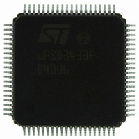
UPSD3433EB40U6 STMicroelectronics, UPSD3433EB40U6 Datasheet - Page 69

UPSD3433EB40U6
Manufacturer Part Number
UPSD3433EB40U6
Description
MCU 8BIT 8032 128KB FLASH 80TQFP
Manufacturer
STMicroelectronics
Series
µPSDr
Datasheet
1.UPSD3434EB40T6.pdf
(293 pages)
Specifications of UPSD3433EB40U6
Core Processor
8032
Core Size
8-Bit
Speed
40MHz
Connectivity
I²C, IrDA, SPI, UART/USART, USB
Peripherals
LVD, POR, PWM, WDT
Number Of I /o
46
Program Memory Size
160KB (160K x 8)
Program Memory Type
FLASH
Ram Size
8K x 8
Voltage - Supply (vcc/vdd)
3 V ~ 5.5 V
Data Converters
A/D 8x10b
Oscillator Type
Internal
Operating Temperature
-40°C ~ 85°C
Package / Case
80-TQFP, 80-VQFP
For Use With
497-5518 - EVAL BOARD RFID READER497-5046 - KIT TOOL FOR ST7/UPSD/STR7 MCU
Lead Free Status / RoHS Status
Lead free / RoHS Compliant
Eeprom Size
-
Other names
497-5660
Available stocks
Company
Part Number
Manufacturer
Quantity
Price
Company:
Part Number:
UPSD3433EB40U6
Manufacturer:
STMicroelectronics
Quantity:
10 000
- Current page: 69 of 293
- Download datasheet (5Mb)
uPSD34xx
17
17.1
I/O ports of mcu module
The MCU Module has three 8-bit I/O ports: Port 1, Port 3, and Port 4. The PSD Module has
four other I/O ports: Port A, B, C, and D. This section describes only the I/O ports on the
MCU Module.
I/O ports will function as bi-directional General Purpose I/O (GPIO), but the port pins can
have alternate functions assigned at run-time by writing to specific SFRs. The default
operating mode (during and after reset) for all three ports is GPIO input mode. Port pins that
have no external connection will not float because each pin has an internal weak pull-up
(~150K ohms) to V
I/O ports 3 and 4 are 5V tolerant, meaning they can be driven/pulled externally up to 5.5V
without damage. The pins on Port 4 have a higher current capability than the pins on Ports 1
and 3.
Three additional MCU ports (only on 80-pin uPSD34xx devices) are dedicated to bring out
the 8032 MCU address, data, and control signals to external pins. One port, named
MCUAD[7:0], has eight multiplexed address/data bidirectional signals. The third port has
MCU bus control outputs: read, write, program fetch, and address latch. These ports are
typically used to connect external parallel peripherals and memory devices, but they may
NOT be used as GPIO. Notice that the eight upper address signals do not come out to pins
on the port. If high-order address signals are required on external pins (MCU addresses
A[15:8]), then these address signals can be brought out as needed to PLD output pins or to
the Address Out mode pins on PSD Module ports. See PSD Module section,
“Section 28.5.39: Latched address output mode on page 232
Figure 16 on page 71
Each of the 24 pins on three ports, P1, P3, and P4, may be individually routed on a pin-by-
pin basis to a desired function.
MCU port operating modes
MCU port pins can operate as GPIO or as alternate functions (see
through
Depending on the selected pin function, a particular pin operating mode will automatically
be used:
●
●
●
●
●
●
●
●
GPIO - Quasi-bidirectional mode
UART0, UART1 - Quasi-bidirectional mode
SPI - Quasi-bidirectional mode
I2C - Open drain mode
ADC - Analog input mode
PCA output - Push-Pull mode
PCA input - Input only (Quasi-bidirectional)
Timer 0,1,2 - Input only (Quasi-bidirectional)
Figure 19 on page
CC
.
represents the flexibility of pin function routing controlled by the SFRs.
72).
for details.
I/O ports of mcu module
Figure 17 on page 71
69/293
Related parts for UPSD3433EB40U6
Image
Part Number
Description
Manufacturer
Datasheet
Request
R

Part Number:
Description:
MCU 8BIT 8032 128KB FLASH 80TQFP
Manufacturer:
STMicroelectronics
Datasheet:

Part Number:
Description:
MCU 8BIT 8032 128KB FLASH 52TQFP
Manufacturer:
STMicroelectronics
Datasheet:

Part Number:
Description:
STMicroelectronics [RIPPLE-CARRY BINARY COUNTER/DIVIDERS]
Manufacturer:
STMicroelectronics
Datasheet:

Part Number:
Description:
STMicroelectronics [LIQUID-CRYSTAL DISPLAY DRIVERS]
Manufacturer:
STMicroelectronics
Datasheet:

Part Number:
Description:
BOARD EVAL FOR MEMS SENSORS
Manufacturer:
STMicroelectronics
Datasheet:

Part Number:
Description:
NPN TRANSISTOR POWER MODULE
Manufacturer:
STMicroelectronics
Datasheet:

Part Number:
Description:
TURBOSWITCH ULTRA-FAST HIGH VOLTAGE DIODE
Manufacturer:
STMicroelectronics
Datasheet:

Part Number:
Description:
Manufacturer:
STMicroelectronics
Datasheet:

Part Number:
Description:
DIODE / SCR MODULE
Manufacturer:
STMicroelectronics
Datasheet:

Part Number:
Description:
DIODE / SCR MODULE
Manufacturer:
STMicroelectronics
Datasheet:

Part Number:
Description:
Search -----> STE16N100
Manufacturer:
STMicroelectronics
Datasheet:

Part Number:
Description:
Search ---> STE53NA50
Manufacturer:
STMicroelectronics
Datasheet:


