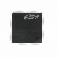
C8051F066-GQ Silicon Laboratories Inc, C8051F066-GQ Datasheet - Page 295

C8051F066-GQ
Manufacturer Part Number
C8051F066-GQ
Description
MCU 8-Bit C8051F06x 8051 CISC 32KB Flash 3.3V 100-Pin TQFP
Manufacturer
Silicon Laboratories Inc
Series
C8051F06xr
Specifications of C8051F066-GQ
Package
100TQFP
Device Core
8051
Family Name
C8051F06x
Maximum Speed
25 MHz
Operating Supply Voltage
3.3 V
Data Bus Width
8 Bit
Number Of Programmable I/os
59
Interface Type
I2C/SMBus/SPI/UART
On-chip Adc
2-chx16-bit
Number Of Timers
5
Ram Size
4.25 KB
Program Memory Size
32 KB
Program Memory Type
Flash
Operating Temperature
-40 to 85 °C
Core Processor
8051
Core Size
8-Bit
Speed
25MHz
Connectivity
EBI/EMI, SMBus (2-Wire/I²C), SPI, UART/USART
Peripherals
Brown-out Detect/Reset, POR, PWM, WDT
Number Of I /o
59
Voltage - Supply (vcc/vdd)
2.7 V ~ 3.6 V
Data Converters
A/D 2x16b
Oscillator Type
Internal
Package / Case
100-TQFP, 100-VQFP
Lead Free Status / RoHS Status
Lead free / RoHS Compliant
Eeprom Size
-
Lead Free Status / RoHS Status
Lead free / RoHS Compliant
Other names
336-1221
Available stocks
Company
Part Number
Manufacturer
Quantity
Price
Company:
Part Number:
C8051F066-GQ
Manufacturer:
Silicon Laboratories Inc
Quantity:
10 000
Company:
Part Number:
C8051F066-GQR
Manufacturer:
Silicon Laboratories Inc
Quantity:
10 000
- Current page: 295 of 328
- Download datasheet (2Mb)
C8051F060/1/2/3/4/5/6/7
24.2. Timer 2, Timer 3, and Timer 4
Timers 2, 3, and 4 are 16-bit counter/timers, each formed by two 8-bit SFRs: TMRnL (low byte) and
TMRnH (high byte) where n = 2, 3, and 4 for timers 2, 3, and 4 respectively. These timers feature auto-
reload, capture, and toggle output modes with the ability to count up or down. Capture Mode and Auto-
reload mode are selected using bits in the Timer 2, 3, and 4 Control registers (TMRnCN). Toggle output
mode is selected using the Timer 2, 3, and 4 Configuration registers (TMRnCF). These timers may also be
used to generate a square-wave at an external pin. Timers 2, 3, and 4 can use either the system clock
(divided by one, two, or twelve), external clock (divided by eight) or transitions on an external input pin as
its clock source. Timer 2 and 3 can be used to start an ADC Data Conversion and Timers 2, 3, and 4 can
schedule DAC outputs. Timers 1, 2, 3, or 4 may be used to generate baud rates for UART 0. Only Timer 1
can be used to generate baud rates for UART 1.
The Counter/Timer Select bit C/Tn bit (TMRnCN.1) configures the peripheral as a counter or timer. Clear-
ing C/Tn configures the Timer to be in a timer mode (i.e., the selected timer clock source as the input for
the timer). When C/Tn is set to 1, the timer is configured as a counter (i.e., high-to-low transitions at the Tn
input pin increment (or decrement) the counter/timer register. Refer to
Section “18.1. Ports 0 through 3 and
the Priority Crossbar Decoder” on page 205
for information on selecting and configuring external I/O pins
for digital peripherals, such as the Tn pin.
Timer 2, 3, and 4 can use either SYSCLK, SYSCLK divided by 2, SYSCLK divided by 12, an external clock
divided by 8, or high-to-low transitions on the Tn input pin as its clock source when operating in Counter/
Timer with Capture mode. Clearing the C/Tn bit (TnCON.1) selects the system clock/external clock as the
input for the timer. The Timer Clock Select bits TnM0 and TnM1 in TMRnCF can be used to select the sys-
tem clock undivided, system clock divided by two, system clock divided by 12, or an external clock pro-
vided at the XTAL1/XTAL2 pins divided by 8 (see Figure 24.14). When C/Tn is set to logic 1, a high-to-low
transition at the Tn input pin increments the counter/timer register (i.e., configured as a counter).
24.2.1. Configuring Timer 2, 3, and 4 to Count Down
Timers 2, 3, and 4 have the ability to count down. When the timer’s respective Decrement Enable Bit
(DCENn) in the Timer Configuration Register (See Figure 24.14) is set to ‘1’, the timer can then count up or
down. When DCENn = 1, the direction of the timer’s count is controlled by the TnEX pin’s logic level. When
TnEX = 1, the counter/timer will count up; when TnEX = 0, the counter/timer will count down. To use this
feature, TnEX must be enabled in the digital crossbar and configured as a digital input.
Note: When DCENn = 1, other functions of the TnEX input (i.e., capture and auto-reload) are not
available. TnEX will only control the direction of the timer when DCENn = 1.
Rev. 1.2
295
Related parts for C8051F066-GQ
Image
Part Number
Description
Manufacturer
Datasheet
Request
R
Part Number:
Description:
SMD/C°/SINGLE-ENDED OUTPUT SILICON OSCILLATOR
Manufacturer:
Silicon Laboratories Inc
Part Number:
Description:
Manufacturer:
Silicon Laboratories Inc
Datasheet:
Part Number:
Description:
N/A N/A/SI4010 AES KEYFOB DEMO WITH LCD RX
Manufacturer:
Silicon Laboratories Inc
Datasheet:
Part Number:
Description:
N/A N/A/SI4010 SIMPLIFIED KEY FOB DEMO WITH LED RX
Manufacturer:
Silicon Laboratories Inc
Datasheet:
Part Number:
Description:
N/A/-40 TO 85 OC/EZLINK MODULE; F930/4432 HIGH BAND (REV E/B1)
Manufacturer:
Silicon Laboratories Inc
Part Number:
Description:
EZLink Module; F930/4432 Low Band (rev e/B1)
Manufacturer:
Silicon Laboratories Inc
Part Number:
Description:
I°/4460 10 DBM RADIO TEST CARD 434 MHZ
Manufacturer:
Silicon Laboratories Inc
Part Number:
Description:
I°/4461 14 DBM RADIO TEST CARD 868 MHZ
Manufacturer:
Silicon Laboratories Inc
Part Number:
Description:
I°/4463 20 DBM RFSWITCH RADIO TEST CARD 460 MHZ
Manufacturer:
Silicon Laboratories Inc
Part Number:
Description:
I°/4463 20 DBM RADIO TEST CARD 868 MHZ
Manufacturer:
Silicon Laboratories Inc
Part Number:
Description:
I°/4463 27 DBM RADIO TEST CARD 868 MHZ
Manufacturer:
Silicon Laboratories Inc
Part Number:
Description:
I°/4463 SKYWORKS 30 DBM RADIO TEST CARD 915 MHZ
Manufacturer:
Silicon Laboratories Inc
Part Number:
Description:
N/A N/A/-40 TO 85 OC/4463 RFMD 30 DBM RADIO TEST CARD 915 MHZ
Manufacturer:
Silicon Laboratories Inc
Part Number:
Description:
I°/4463 20 DBM RADIO TEST CARD 169 MHZ
Manufacturer:
Silicon Laboratories Inc


