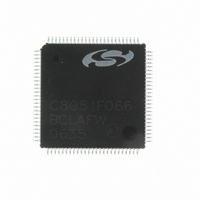
C8051F066-GQ Silicon Laboratories Inc, C8051F066-GQ Datasheet - Page 6

C8051F066-GQ
Manufacturer Part Number
C8051F066-GQ
Description
MCU 8-Bit C8051F06x 8051 CISC 32KB Flash 3.3V 100-Pin TQFP
Manufacturer
Silicon Laboratories Inc
Series
C8051F06xr
Specifications of C8051F066-GQ
Package
100TQFP
Device Core
8051
Family Name
C8051F06x
Maximum Speed
25 MHz
Operating Supply Voltage
3.3 V
Data Bus Width
8 Bit
Number Of Programmable I/os
59
Interface Type
I2C/SMBus/SPI/UART
On-chip Adc
2-chx16-bit
Number Of Timers
5
Ram Size
4.25 KB
Program Memory Size
32 KB
Program Memory Type
Flash
Operating Temperature
-40 to 85 °C
Core Processor
8051
Core Size
8-Bit
Speed
25MHz
Connectivity
EBI/EMI, SMBus (2-Wire/I²C), SPI, UART/USART
Peripherals
Brown-out Detect/Reset, POR, PWM, WDT
Number Of I /o
59
Voltage - Supply (vcc/vdd)
2.7 V ~ 3.6 V
Data Converters
A/D 2x16b
Oscillator Type
Internal
Package / Case
100-TQFP, 100-VQFP
Lead Free Status / RoHS Status
Lead free / RoHS Compliant
Eeprom Size
-
Lead Free Status / RoHS Status
Lead free / RoHS Compliant
Other names
336-1221
Available stocks
Company
Part Number
Manufacturer
Quantity
Price
Company:
Part Number:
C8051F066-GQ
Manufacturer:
Silicon Laboratories Inc
Quantity:
10 000
Company:
Part Number:
C8051F066-GQR
Manufacturer:
Silicon Laboratories Inc
Quantity:
10 000
- Current page: 6 of 328
- Download datasheet (2Mb)
C8051F060/1/2/3/4/5/6/7
19. Controller Area Network (CAN0, C8051F060/1/2/3) ........................................... 225
229
20. System Management BUS / I2C BUS (SMBUS0)................................................ 235
21. Enhanced Serial Peripheral Interface (SPI0)...................................................... 251
6
18.2.Ports 4 through 7 (C8051F060/2/4/6 only) ..................................................... 219
19.1.Bosch CAN Controller Operation.................................................................... 227
19.2.CAN Registers................................................................................................ 228
20.1.Supporting Documents ................................................................................... 236
20.2.SMBus Protocol.............................................................................................. 236
20.3.SMBus Transfer Modes.................................................................................. 238
20.4.SMBus Special Function Registers ................................................................ 241
21.1.Signal Descriptions......................................................................................... 252
21.2.SPI0 Master Mode Operation ......................................................................... 253
21.3.SPI0 Slave Mode Operation ........................................................................... 255
21.4.SPI0 Interrupt Sources ................................................................................... 255
18.1.5.Configuring Port 1 and 2 pins as Analog Inputs..................................... 207
18.1.6.Crossbar Pin Assignment Example........................................................ 208
18.2.1.Configuring Ports which are not Pinned Out .......................................... 219
18.2.2.Configuring the Output Modes of the Port Pins...................................... 219
18.2.3.Configuring Port Pins as Digital Inputs................................................... 219
18.2.4.Weak Pull-ups ........................................................................................ 219
18.2.5.External Memory Interface ..................................................................... 220
19.2.1.CAN Controller Protocol Registers......................................................... 228
19.2.2.Message Object Interface Registers ...................................................... 228
19.2.3.Message Handler Registers................................................................... 228
19.2.4.CIP-51 MCU Special Function Registers ............................................... 229
19.2.5.Using CAN0ADR, CAN0DATH, and CANDATL To Access CAN Registers
19.2.6.CAN0ADR Autoincrement Feature ........................................................ 229
20.2.1.Arbitration............................................................................................... 237
20.2.2.Clock Low Extension.............................................................................. 237
20.2.3.SCL Low Timeout................................................................................... 237
20.2.4.SCL High (SMBus Free) Timeout .......................................................... 237
20.3.1.Master Transmitter Mode ....................................................................... 238
20.3.2.Master Receiver Mode ........................................................................... 238
20.3.3.Slave Transmitter Mode ......................................................................... 239
20.3.4.Slave Receiver Mode ............................................................................. 239
20.4.1.Control Register ..................................................................................... 241
20.4.2.Clock Rate Register ............................................................................... 244
20.4.3.Data Register ......................................................................................... 245
20.4.4.Address Register.................................................................................... 245
20.4.5.Status Register....................................................................................... 246
21.1.1.Master Out, Slave In (MOSI).................................................................. 252
21.1.2.Master In, Slave Out (MISO).................................................................. 252
21.1.3.Serial Clock (SCK) ................................................................................. 252
21.1.4.Slave Select (NSS) ................................................................................ 252
Rev. 1.2
Related parts for C8051F066-GQ
Image
Part Number
Description
Manufacturer
Datasheet
Request
R
Part Number:
Description:
SMD/C°/SINGLE-ENDED OUTPUT SILICON OSCILLATOR
Manufacturer:
Silicon Laboratories Inc
Part Number:
Description:
Manufacturer:
Silicon Laboratories Inc
Datasheet:
Part Number:
Description:
N/A N/A/SI4010 AES KEYFOB DEMO WITH LCD RX
Manufacturer:
Silicon Laboratories Inc
Datasheet:
Part Number:
Description:
N/A N/A/SI4010 SIMPLIFIED KEY FOB DEMO WITH LED RX
Manufacturer:
Silicon Laboratories Inc
Datasheet:
Part Number:
Description:
N/A/-40 TO 85 OC/EZLINK MODULE; F930/4432 HIGH BAND (REV E/B1)
Manufacturer:
Silicon Laboratories Inc
Part Number:
Description:
EZLink Module; F930/4432 Low Band (rev e/B1)
Manufacturer:
Silicon Laboratories Inc
Part Number:
Description:
I°/4460 10 DBM RADIO TEST CARD 434 MHZ
Manufacturer:
Silicon Laboratories Inc
Part Number:
Description:
I°/4461 14 DBM RADIO TEST CARD 868 MHZ
Manufacturer:
Silicon Laboratories Inc
Part Number:
Description:
I°/4463 20 DBM RFSWITCH RADIO TEST CARD 460 MHZ
Manufacturer:
Silicon Laboratories Inc
Part Number:
Description:
I°/4463 20 DBM RADIO TEST CARD 868 MHZ
Manufacturer:
Silicon Laboratories Inc
Part Number:
Description:
I°/4463 27 DBM RADIO TEST CARD 868 MHZ
Manufacturer:
Silicon Laboratories Inc
Part Number:
Description:
I°/4463 SKYWORKS 30 DBM RADIO TEST CARD 915 MHZ
Manufacturer:
Silicon Laboratories Inc
Part Number:
Description:
N/A N/A/-40 TO 85 OC/4463 RFMD 30 DBM RADIO TEST CARD 915 MHZ
Manufacturer:
Silicon Laboratories Inc
Part Number:
Description:
I°/4463 20 DBM RADIO TEST CARD 169 MHZ
Manufacturer:
Silicon Laboratories Inc


