MC908QC16CDZE Freescale Semiconductor, MC908QC16CDZE Datasheet - Page 99
MC908QC16CDZE
Manufacturer Part Number
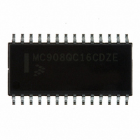
MC908QC16CDZE
Description
IC MCU 8BIT 16K FLASH 28-SOIC
Manufacturer
Freescale Semiconductor
Series
HC08r
Specifications of MC908QC16CDZE
Core Processor
HC08
Core Size
8-Bit
Speed
8MHz
Connectivity
SCI, SPI
Peripherals
LVD, POR, PWM
Number Of I /o
24
Program Memory Size
16KB (16K x 8)
Program Memory Type
FLASH
Ram Size
512 x 8
Voltage - Supply (vcc/vdd)
3 V ~ 5.5 V
Data Converters
A/D 10x10b
Oscillator Type
Internal
Operating Temperature
-40°C ~ 85°C
Package / Case
28-SOIC (7.5mm Width)
Processor Series
HC08QC
Core
HC08
Data Bus Width
8 bit
Data Ram Size
512 B
Interface Type
ESCI/SPI
Maximum Clock Frequency
8 MHz
Number Of Programmable I/os
26
Number Of Timers
6
Maximum Operating Temperature
+ 85 C
Mounting Style
SMD/SMT
Development Tools By Supplier
FSICEBASE, M68CBL05AE, DEMO908QB8, DEMO908QC16
Minimum Operating Temperature
- 40 C
On-chip Adc
10-ch x 10-bit
For Use With
DEMO908QC16 - BOARD DEMO FOR MC908QC16
Lead Free Status / RoHS Status
Lead free / RoHS Compliant
Eeprom Size
-
Lead Free Status / Rohs Status
Lead free / RoHS Compliant
Available stocks
Company
Part Number
Manufacturer
Quantity
Price
Company:

Part Number:
MC908QC16CDZE
Manufacturer:
FREESCALE
Quantity:
1 600
Part Number:
MC908QC16CDZE
Manufacturer:
FREESCALE
Quantity:
20 000


Functional Description
10.3.1.2 XTAL Oscillator Clock (XTALCLK)
XTALCLK is the XTAL oscillator output signal. It runs at the full speed of the crystal (f
) and comes
XCLK
directly from the crystal oscillator circuit.
Figure 10-2
shows only the logical relation of XTALCLK to OSC1
and OSC2 and may not represent the actual circuitry. The duty cycle of XTALCLK is unknown and may
depend on the crystal and other external factors. The frequency of XTALCLK can be unstable at start up.
10.3.1.3 RC Oscillator Clock (RCCLK)
RCCLK is the RC oscillator output signal. Its frequency is directly proportional to the time constant of the
external R (R
) and internal C.
Figure 10-3
shows only the logical relation of RCCLK to OSC1 and may
EXT
not represent the actual circuitry.
10.3.1.4 Internal Oscillator Clock (INTCLK)
INTCLK is the internal oscillator output signal. INTCLK is software selectable to be nominally 25.6 MHz,
12.8 MHz, 8.0 MHz, or 4.0 MHz. INTCLK can be digitally adjusted using the oscillator trimming feature of
the OSCTRIM register (see
10.3.2.1 Internal Oscillator
Trimming).
10.3.1.5 Bus Clock Times 4 (BUSCLKX4)
BUSCLKX4 is the same frequency as the input clock (XTALCLK, RCCLK, or INTCLK). This signal is
driven to the SIM module and is used during recovery from reset and stop and is the clock source for the
COP module.
10.3.1.6 Bus Clock Times 2 (BUSCLKX2)
The frequency of this signal is equal to half of the BUSCLKX4. This signal is driven to the SIM for
generation of the bus clocks used by the CPU and other modules on the MCU. BUSCLKX2 will be divided
by two in the SIM. The internal bus frequency is one fourth of the XTALCLK, RCCLK, or INTCLK
frequency.
10.3.2 Internal Oscillator
The internal oscillator circuit is designed for use with no external components to provide a clock source
with a tolerance of less than 25%untrimmed. An 8-bit register (OSCTRIM) allows the digital adjustment
to a tolerance of ACC
. See the oscillator characteristics in the Electrical section of this data sheet.
INT
The internal oscillator is capable of generating clocks of 25.6 MHz, 12.8 MHz, 8.0 MHz, or 4.0 MHz
(INTCLK) resulting in a bus frequency (INTCLK divided by 4) of 6.4 MHz, 3.2 MHz, 2.0 MHz, or 1.0 MHz
respectively. The bus clock is software selectable and defaults to the 1.0-MHz bus out of reset. Users can
increase the bus frequency based on the voltage range of their application.
Figure 10-3
shows how BUSCLKX4 is derived from INTCLK and OSC2 can output BUSCLKX4 by setting
OSC2EN.
10.3.2.1 Internal Oscillator Trimming
OSCTRIM allows a clock period adjustment of +127 and –128 steps. Increasing the OSCTRIM value
increases the clock period, which decreases the clock frequency. Trimming allows the internal clock
frequency to be fine tuned to the target frequency.
All devices are factory programmed with a trim value that is stored in FLASH memory at location $FFC0.
This trim value is not automatically loaded into OSCTRIM register. User software must copy the trim value
MC68HC908QC16 • MC68HC908QC8 • MC68HC908QC4 Data Sheet, Rev. 5
Freescale Semiconductor
99
Related parts for MC908QC16CDZE
Image
Part Number
Description
Manufacturer
Datasheet
Request
R

Part Number:
Description:
Manufacturer:
Freescale Semiconductor, Inc
Datasheet:
Part Number:
Description:
Manufacturer:
Freescale Semiconductor, Inc
Datasheet:
Part Number:
Description:
Manufacturer:
Freescale Semiconductor, Inc
Datasheet:
Part Number:
Description:
Manufacturer:
Freescale Semiconductor, Inc
Datasheet:
Part Number:
Description:
Manufacturer:
Freescale Semiconductor, Inc
Datasheet:
Part Number:
Description:
Manufacturer:
Freescale Semiconductor, Inc
Datasheet:
Part Number:
Description:
Manufacturer:
Freescale Semiconductor, Inc
Datasheet:
Part Number:
Description:
Manufacturer:
Freescale Semiconductor, Inc
Datasheet:
Part Number:
Description:
Manufacturer:
Freescale Semiconductor, Inc
Datasheet:
Part Number:
Description:
Manufacturer:
Freescale Semiconductor, Inc
Datasheet:
Part Number:
Description:
Manufacturer:
Freescale Semiconductor, Inc
Datasheet:
Part Number:
Description:
Manufacturer:
Freescale Semiconductor, Inc
Datasheet:
Part Number:
Description:
Manufacturer:
Freescale Semiconductor, Inc
Datasheet:
Part Number:
Description:
Manufacturer:
Freescale Semiconductor, Inc
Datasheet:
Part Number:
Description:
Manufacturer:
Freescale Semiconductor, Inc
Datasheet: