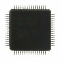
HD64F3664FPV Renesas Electronics America, HD64F3664FPV Datasheet - Page 173

HD64F3664FPV
Manufacturer Part Number
HD64F3664FPV
Description
IC H8/3664 MCU FLASH 32K 64LQFP
Manufacturer
Renesas Electronics America
Series
H8® H8/300H Tinyr
Specifications of HD64F3664FPV
Core Size
16-Bit
Program Memory Size
32KB (32K x 8)
Oscillator Type
External
Core Processor
H8/300H
Speed
16MHz
Connectivity
I²C, SCI
Peripherals
PWM, WDT
Number Of I /o
29
Program Memory Type
FLASH
Ram Size
2K x 8
Voltage - Supply (vcc/vdd)
3 V ~ 5.5 V
Data Converters
A/D 8x10b
Operating Temperature
-20°C ~ 75°C
Package / Case
64-LQFP
No. Of I/o's
29
Ram Memory Size
2KB
Cpu Speed
16MHz
No. Of Timers
4
Digital Ic Case Style
LQFP
Supply Voltage
RoHS Compliant
Controller Family/series
H8/300H
Rohs Compliant
Yes
Lead Free Status / RoHS Status
Lead free / RoHS Compliant
Eeprom Size
-
Lead Free Status / RoHS Status
Lead free / RoHS Compliant
Available stocks
Company
Part Number
Manufacturer
Quantity
Price
Company:
Part Number:
HD64F3664FPV
Manufacturer:
MURATA
Quantity:
34 000
Company:
Part Number:
HD64F3664FPV
Manufacturer:
HD
Quantity:
465
Company:
Part Number:
HD64F3664FPV
Manufacturer:
Renesas Electronics America
Quantity:
10 000
Part Number:
HD64F3664FPV
Manufacturer:
RENESAS/瑞萨
Quantity:
20 000
- Current page: 173 of 446
- Download datasheet (3Mb)
10.4
10.4.1
When bit TMA3 in TMA is cleared to 0, timer A functions as an 8-bit interval timer.
Upon reset, TCA is cleared to H'00 and bit TMA3 is cleared to 0, so up-counting of timer A
resume immediately as an interval timer. The clock input to timer A is selected by bits TMA2 to
TMA0 in TMA; any of eight internal clock signals output by prescaler S can be selected.
After the count value in TCA reaches H'FF, the next clock signal input causes timer A to
overflow, setting bit IRRTA to 1 in interrupt Flag Register 1 (IRR1). If IENTA = 1 in interrupt
enable register 1 (IENR1), a CPU interrupt is requested. At overflow, TCA returns to H'00 and
starts counting up again. In this mode timer A functions as an interval timer that generates an
overflow output at intervals of 256 input clock pulses.
10.4.2
When bit TMA3 in TMA is set to 1, timer A functions as a clock-timer base by counting clock
signals output by prescaler W. When a clock signal is input after the TCA counter value has
become H'FF, timer A overflows and IRRTA in IRR1 is set to 1. At that time, an interrupt request
is generated to the CPU if IENTA in the interrupt enable register 1 (IENR1) is 1. The overflow
period of timer A is set by bits TMA1 and TMA0 in TMA. A choice of four periods is available.
In clock time base operation (TMA3 = 1), setting bit TMA2 to 1 clears both TCA and prescaler W
to H'00.
10.4.3
Setting bit TMOW in port mode register 1 (PMR1) to 1 causes a clock signal to be output at pin
TMOW. Eight different clock output signals can be selected by means of bits TMA7 to TMA5 in
TMA. The system clock divided by 32, 16, 8, or 4 can be output in active mode and sleep mode. A
32.768 kHz signal divided by 32, 16, 8, or 4 can be output in active mode, sleep mode, and
subactive mode.
Operation
Interval Timer Operation
Clock Time Base Operation
Clock Output
Rev. 6.00 Mar. 24, 2006 Page 143 of 412
Section 10 Timer A
REJ09B0142-0600
Related parts for HD64F3664FPV
Image
Part Number
Description
Manufacturer
Datasheet
Request
R

Part Number:
Description:
KIT STARTER FOR M16C/29
Manufacturer:
Renesas Electronics America
Datasheet:

Part Number:
Description:
KIT STARTER FOR R8C/2D
Manufacturer:
Renesas Electronics America
Datasheet:

Part Number:
Description:
R0K33062P STARTER KIT
Manufacturer:
Renesas Electronics America
Datasheet:

Part Number:
Description:
KIT STARTER FOR R8C/23 E8A
Manufacturer:
Renesas Electronics America
Datasheet:

Part Number:
Description:
KIT STARTER FOR R8C/25
Manufacturer:
Renesas Electronics America
Datasheet:

Part Number:
Description:
KIT STARTER H8S2456 SHARPE DSPLY
Manufacturer:
Renesas Electronics America
Datasheet:

Part Number:
Description:
KIT STARTER FOR R8C38C
Manufacturer:
Renesas Electronics America
Datasheet:

Part Number:
Description:
KIT STARTER FOR R8C35C
Manufacturer:
Renesas Electronics America
Datasheet:

Part Number:
Description:
KIT STARTER FOR R8CL3AC+LCD APPS
Manufacturer:
Renesas Electronics America
Datasheet:

Part Number:
Description:
KIT STARTER FOR RX610
Manufacturer:
Renesas Electronics America
Datasheet:

Part Number:
Description:
KIT STARTER FOR R32C/118
Manufacturer:
Renesas Electronics America
Datasheet:

Part Number:
Description:
KIT DEV RSK-R8C/26-29
Manufacturer:
Renesas Electronics America
Datasheet:

Part Number:
Description:
KIT STARTER FOR SH7124
Manufacturer:
Renesas Electronics America
Datasheet:

Part Number:
Description:
KIT STARTER FOR H8SX/1622
Manufacturer:
Renesas Electronics America
Datasheet:


