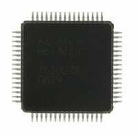
HD64F3664FPV Renesas Electronics America, HD64F3664FPV Datasheet - Page 310

HD64F3664FPV
Manufacturer Part Number
HD64F3664FPV
Description
IC H8/3664 MCU FLASH 32K 64LQFP
Manufacturer
Renesas Electronics America
Series
H8® H8/300H Tinyr
Specifications of HD64F3664FPV
Core Size
16-Bit
Program Memory Size
32KB (32K x 8)
Oscillator Type
External
Core Processor
H8/300H
Speed
16MHz
Connectivity
I²C, SCI
Peripherals
PWM, WDT
Number Of I /o
29
Program Memory Type
FLASH
Ram Size
2K x 8
Voltage - Supply (vcc/vdd)
3 V ~ 5.5 V
Data Converters
A/D 8x10b
Operating Temperature
-20°C ~ 75°C
Package / Case
64-LQFP
No. Of I/o's
29
Ram Memory Size
2KB
Cpu Speed
16MHz
No. Of Timers
4
Digital Ic Case Style
LQFP
Supply Voltage
RoHS Compliant
Controller Family/series
H8/300H
Rohs Compliant
Yes
Lead Free Status / RoHS Status
Lead free / RoHS Compliant
Eeprom Size
-
Lead Free Status / RoHS Status
Lead free / RoHS Compliant
Available stocks
Company
Part Number
Manufacturer
Quantity
Price
Company:
Part Number:
HD64F3664FPV
Manufacturer:
MURATA
Quantity:
34 000
Company:
Part Number:
HD64F3664FPV
Manufacturer:
HD
Quantity:
465
Company:
Part Number:
HD64F3664FPV
Manufacturer:
Renesas Electronics America
Quantity:
10 000
Part Number:
HD64F3664FPV
Manufacturer:
RENESAS/瑞萨
Quantity:
20 000
- Current page: 310 of 446
- Download datasheet (3Mb)
Section 16 A/D Converter
16.3.3
ADCR enables A/D conversion started by an external trigger signal.
Rev. 6.00 Mar. 24, 2006 Page 280 of 412
REJ09B0142-0600
Bit
2
1
0
Bit
7
6 to 1
0
A/D Control Register (ADCR)
Bit Name
CH2
CH1
CH0
Bit Name
TRGE
—
—
Initial
Value
0
0
0
Initial
Value
0
All 1
0
R/W
R/W
R/W
R/W
R/W
R/W
—
R/W
Description
Channel Select 0 to 2
Select analog input channels.
When SCAN = 0
000: AN0
001: AN1
010: AN2
011: AN3
100: AN4
101: AN5
110: AN6
111: AN7
AN4, AN5, AN6, and AN7 do not exist in the 42-pin
version.
Description
Trigger Enable
A/D conversion is started at the falling edge and the
rising edge of the external trigger signal (ADTRG)
when this bit is set to 1.
The selection between the falling edge and rising edge
of the external trigger pin (ADTRG) conforms to the
WPEG5 bit in the interrupt edge select register 2
(IEGR2).
Reserved
These bits are always read as 1.
Reserved
Do not set this bit to 1, though the bit is
readable/writable.
When SCAN = 1
000: AN0
001: AN0 to AN1
010: AN0 to AN2
011: AN0 to AN3
100: AN4
101: AN4 to AN5
110: AN4 to AN6
111: AN4 to AN7
Related parts for HD64F3664FPV
Image
Part Number
Description
Manufacturer
Datasheet
Request
R

Part Number:
Description:
KIT STARTER FOR M16C/29
Manufacturer:
Renesas Electronics America
Datasheet:

Part Number:
Description:
KIT STARTER FOR R8C/2D
Manufacturer:
Renesas Electronics America
Datasheet:

Part Number:
Description:
R0K33062P STARTER KIT
Manufacturer:
Renesas Electronics America
Datasheet:

Part Number:
Description:
KIT STARTER FOR R8C/23 E8A
Manufacturer:
Renesas Electronics America
Datasheet:

Part Number:
Description:
KIT STARTER FOR R8C/25
Manufacturer:
Renesas Electronics America
Datasheet:

Part Number:
Description:
KIT STARTER H8S2456 SHARPE DSPLY
Manufacturer:
Renesas Electronics America
Datasheet:

Part Number:
Description:
KIT STARTER FOR R8C38C
Manufacturer:
Renesas Electronics America
Datasheet:

Part Number:
Description:
KIT STARTER FOR R8C35C
Manufacturer:
Renesas Electronics America
Datasheet:

Part Number:
Description:
KIT STARTER FOR R8CL3AC+LCD APPS
Manufacturer:
Renesas Electronics America
Datasheet:

Part Number:
Description:
KIT STARTER FOR RX610
Manufacturer:
Renesas Electronics America
Datasheet:

Part Number:
Description:
KIT STARTER FOR R32C/118
Manufacturer:
Renesas Electronics America
Datasheet:

Part Number:
Description:
KIT DEV RSK-R8C/26-29
Manufacturer:
Renesas Electronics America
Datasheet:

Part Number:
Description:
KIT STARTER FOR SH7124
Manufacturer:
Renesas Electronics America
Datasheet:

Part Number:
Description:
KIT STARTER FOR H8SX/1622
Manufacturer:
Renesas Electronics America
Datasheet:


