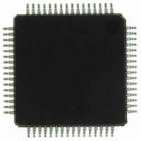
ISP1362BDFA ST-Ericsson Inc, ISP1362BDFA Datasheet - Page 116

ISP1362BDFA
Manufacturer Part Number
ISP1362BDFA
Description
IC USB OTG CONTROLLER 64-LQFP
Manufacturer
ST-Ericsson Inc
Datasheet
1.ISP1362EEUM.pdf
(153 pages)
Specifications of ISP1362BDFA
Controller Type
USB 2.0 Controller
Interface
Parallel/Serial
Voltage - Supply
3 V ~ 3.6 V
Operating Temperature
-40°C ~ 85°C
Mounting Type
Surface Mount
Package / Case
64-LQFP
Lead Free Status / RoHS Status
Lead free / RoHS Compliant
Current - Supply
-
Other names
568-1219
ISP1362BD,151
ISP1362BD-S
ISP1362BD,151
ISP1362BD-S
Available stocks
Company
Part Number
Manufacturer
Quantity
Price
Company:
Part Number:
ISP1362BDFA
Manufacturer:
STE
Quantity:
5
NXP Semiconductors
ISP1362_5
Product data sheet
15.2.1 Write or read endpoint buffer (R/W: 10h,12h to 1Fh/01h to 0Fh)
15.2 Data flow commands
Data flow commands are used to manage data transmission between USB endpoints and
the system microprocessor. Much of the data flow is initiated using an interrupt to the
microprocessor. Data flow commands are used to access endpoints and determine
whether the endpoint buffer memory contains valid data.
Remark: The IN buffer of an endpoint contains input data for the host. The OUT buffer
receives output data from the host.
This command is used to access endpoint buffer memory to read/write. First, the buffer
pointer is reset to the start of the buffer. Following the command, a maximum of (N + 2)
bytes can be written or read, N represents the size of the endpoint buffer. For 16-bit
access, the maximum number of words is (M + 1), with M given as (N + 1) divided by 2.
After each read or write action, the buffer pointer is automatically incremented by two.
In Direct Memory Access (DMA), the first two bytes or the first word (the packet length) is
skipped: transfers start at the third byte or the second word of the endpoint buffer. When
reading, the Peripheral Controller can detect the last byte or word by using the EOP
condition. When writing to a bulk or interrupt endpoint, the endpoint buffer must be
completely filled before sending data to the host. Exception: when a DMA transfer is
stopped by an external EOT condition, the current buffer content (full or not) is sent to the
host.
Remark: Reading data after a Write Endpoint Buffer command or writing data after a
Read Endpoint Buffer command data will cause unpredictable behavior of the Peripheral
Controller.
Code (Hex): 01 to 0F — write (control IN, endpoints 1 to 14)
Code (Hex): 10, 12 to 1F — read (control OUT, endpoints 1 to 14)
Transaction — write or read maximum N + 2 bytes (isochronous endpoint: N
bulk/interrupt endpoint: N
The data in the endpoint buffer memory must be organized as shown in
example of endpoint buffer memory access is given in
Table 123. Endpoint buffer memory organization
Word #
0 (lower byte)
0 (upper byte)
1 (lower byte)
1 (upper byte)
…
M = (N + 1) / 2
Rev. 05 — 8 May 2007
32) (code or data)
Description
packet length (lower byte)
packet length (upper byte)
data byte 1
data byte 2
…
data byte N
Table
Single-chip USB OTG Controller
124.
© NXP B.V. 2007. All rights reserved.
Table
ISP1362
123. An
1023,
115 of 152


