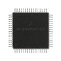
MC68HC705X32CFU Freescale Semiconductor, MC68HC705X32CFU Datasheet - Page 127

MC68HC705X32CFU
Manufacturer Part Number
MC68HC705X32CFU
Description
Manufacturer
Freescale Semiconductor
Datasheet
1.MC68HC705X32CFU.pdf
(232 pages)
Specifications of MC68HC705X32CFU
Cpu Family
HC05
Device Core Size
8b
Frequency (max)
4MHz
Interface Type
SCI
Program Memory Type
EPROM
Program Memory Size
32KB
Total Internal Ram Size
528Byte
# I/os (max)
32
Number Of Timers - General Purpose
1
Operating Supply Voltage (typ)
5V
Operating Supply Voltage (max)
5.5V
Operating Supply Voltage (min)
4.5V
On-chip Adc
8-chx8-bit
Instruction Set Architecture
CISC
Operating Temp Range
-40C to 85C
Operating Temperature Classification
Industrial
Mounting
Surface Mount
Pin Count
64
Package Type
PQFP
Lead Free Status / Rohs Status
Supplier Unconfirmed
Available stocks
Company
Part Number
Manufacturer
Quantity
Price
Part Number:
MC68HC705X32CFU4
Manufacturer:
FREESCALE
Quantity:
20 000
- Current page: 127 of 232
- Download datasheet (6Mb)
Note:
8.1
SFA — Slow or fast mode selection for PLMA
This bit allows the user to select the slow or fast mode of the PLMA pulse length modulation output.
SFB — Slow or fast mode selection for PLMB
This bit allows the user to select the slow or fast mode of the PLMB pulse length modulation output.
The highest speed of the PLM system corresponds to the frequency of the TOF bit being set,
multiplied by 256. The lowest speed of the PLM system corresponds to the frequency of the TOF
bit being set, multiplied by 16. Because the SFA bit and SFB bit are not double buffered, it is
mandatory to set them to the desired values before writing to the PLM registers; not doing so could
temporarily give incorrect values at the PLM outputs.
SM — Slow mode
The SM bit is cleared by external or power-on reset. The SM bit is automatically cleared when
entering STOP mode.
Note:
MC68HC05X16
1 (set)
0 (clear) –
1 (set)
0 (clear) –
1 (set)
0 (clear) –
Miscellaneous
Since the PLM system uses the timer counter, PLM results will be affected while resetting
the timer counter. Both D/A registers are reset to $00 during power-on or external reset.
WAIT mode does not affect the output waveform of the D/A converters.
The bits that are shown shaded in the above representation are explained individually
in the relevant sections of this manual. The complete register plus an explanation of
each bit can be found in
Miscellaneous register
Freescale Semiconductor, Inc.
–
–
–
For More Information On This Product,
(f
SCI, A/D and timer.
Slow mode PLMA (4096 x timer clock period).
Fast mode PLMA (256 x timer clock period).
Slow mode PLMB (4096 x timer clock period).
Fast mode PLMB (256 x timer clock period).
The system runs at a bus speed 16 times lower than normal
The system runs at normal bus speed (f
OSC
/32). SLOW mode affects all sections of the device, including
Address
PULSE LENGTH D/A CONVERTERS
Go to: www.freescale.com
$000C
Section
POR
bit 7
3.8.
INTP
bit 6
INTN
bit 5
INTE
bit 4
OSC
bit 3
SFA
/2).
SFB
bit 2
bit 1
SM
WDOG u001 000u
bit 0
on reset
State
8-3
8
Related parts for MC68HC705X32CFU
Image
Part Number
Description
Manufacturer
Datasheet
Request
R
Part Number:
Description:
Manufacturer:
Freescale Semiconductor, Inc
Datasheet:
Part Number:
Description:
Manufacturer:
Freescale Semiconductor, Inc
Datasheet:
Part Number:
Description:
Manufacturer:
Freescale Semiconductor, Inc
Datasheet:
Part Number:
Description:
Manufacturer:
Freescale Semiconductor, Inc
Datasheet:
Part Number:
Description:
Manufacturer:
Freescale Semiconductor, Inc
Datasheet:
Part Number:
Description:
Manufacturer:
Freescale Semiconductor, Inc
Datasheet:
Part Number:
Description:
Manufacturer:
Freescale Semiconductor, Inc
Datasheet:
Part Number:
Description:
Manufacturer:
Freescale Semiconductor, Inc
Datasheet:
Part Number:
Description:
Manufacturer:
Freescale Semiconductor, Inc
Datasheet:
Part Number:
Description:
Manufacturer:
Freescale Semiconductor, Inc
Datasheet:
Part Number:
Description:
Manufacturer:
Freescale Semiconductor, Inc
Datasheet:
Part Number:
Description:
Manufacturer:
Freescale Semiconductor, Inc
Datasheet:
Part Number:
Description:
Manufacturer:
Freescale Semiconductor, Inc
Datasheet:
Part Number:
Description:
Manufacturer:
Freescale Semiconductor, Inc
Datasheet:
Part Number:
Description:
Manufacturer:
Freescale Semiconductor, Inc
Datasheet:


