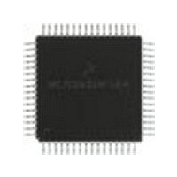
MC68HC705X32CFU Freescale Semiconductor, MC68HC705X32CFU Datasheet - Page 37

MC68HC705X32CFU
Manufacturer Part Number
MC68HC705X32CFU
Description
Manufacturer
Freescale Semiconductor
Datasheet
1.MC68HC705X32CFU.pdf
(232 pages)
Specifications of MC68HC705X32CFU
Cpu Family
HC05
Device Core Size
8b
Frequency (max)
4MHz
Interface Type
SCI
Program Memory Type
EPROM
Program Memory Size
32KB
Total Internal Ram Size
528Byte
# I/os (max)
32
Number Of Timers - General Purpose
1
Operating Supply Voltage (typ)
5V
Operating Supply Voltage (max)
5.5V
Operating Supply Voltage (min)
4.5V
On-chip Adc
8-chx8-bit
Instruction Set Architecture
CISC
Operating Temp Range
-40C to 85C
Operating Temperature Classification
Industrial
Mounting
Surface Mount
Pin Count
64
Package Type
PQFP
Lead Free Status / Rohs Status
Supplier Unconfirmed
Available stocks
Company
Part Number
Manufacturer
Quantity
Price
Part Number:
MC68HC705X32CFU4
Manufacturer:
FREESCALE
Quantity:
20 000
- Current page: 37 of 232
- Download datasheet (6Mb)
2.3.11
The SCLK pin is the clock output pin of the SCI transmitter.
2.3.12
These pins provide control input for an on-chip oscillator circuit. A crystal, ceramic resonator or
external clock signal connected to these pins supplies the oscillator clock. The oscillator frequency
(f
software option which introduces an additional divide by 16 into the oscillator clock, giving an
internal bus frequency of f
2.3.12.1
The circuit shown in
resonator. An internal feedback resistor is provided on-chip between OSC1 and OSC2.
Figure
interface with an AT-cut parallel-resonant quartz crystal resonator in the frequency range specified
for f
outside the specified ranges are to be used. The crystal and associated components should be
mounted as close as possible to the input pins to minimise output distortion and start-up
stabilization time. The manufacturer of the particular crystal being considered should be consulted
for specific information.
2.3.12.2
A ceramic resonator may be used instead of a crystal in cost sensitive applications for frequencies up
to 8MHz external. The circuit shown in
ceramic resonator.
The manufacturer of the particular ceramic resonator being considered should be consulted for specific
information. This option is recommended only for applications that operate at an external clock
frequency of 8MHz or less. Any application requiring an external operating frequency greater that
8MHz should use either a crystal oscillator or an external CMOS compatible clock source.
2.3.12.3
When using an external clock the OSC1 and OSC2 pins should be driven in antiphase, as shown
in
external clock input. The equivalent specification of the external clock source should be used in
lieu of t
MC68HC05X16
OSC
Figure
OSC
) is divided by two, four, eight or ten to give the internal bus frequency (f
2-6(d) lists the recommended capacitance values. The internal oscillator is designed to
OXOV
(see
2-6(c). The t
or t
Section
SCLK
OSC1, OSC2
Crystal
Ceramic resonator
External clock
Freescale Semiconductor, Inc.
ILCH
Figure
.
For More Information On This Product,
MODES OF OPERATION AND PIN DESCRIPTIONS
OXOV
Figure
12.4). Use of an external CMOS oscillator is recommended when crystals
2-6(d) lists the recommended capacitance and feedback resistance values.
OSC
or t
2-6(a) is recommended when using either a crystal or a ceramic
Go to: www.freescale.com
/32, /64, /128 or /160.
ILCH
specifications (see
Figure
2-6(a) is recommended when using either a crystal or a
Section
12.4) do not apply when using an
OP
). There is also a
2-13
2
Related parts for MC68HC705X32CFU
Image
Part Number
Description
Manufacturer
Datasheet
Request
R
Part Number:
Description:
Manufacturer:
Freescale Semiconductor, Inc
Datasheet:
Part Number:
Description:
Manufacturer:
Freescale Semiconductor, Inc
Datasheet:
Part Number:
Description:
Manufacturer:
Freescale Semiconductor, Inc
Datasheet:
Part Number:
Description:
Manufacturer:
Freescale Semiconductor, Inc
Datasheet:
Part Number:
Description:
Manufacturer:
Freescale Semiconductor, Inc
Datasheet:
Part Number:
Description:
Manufacturer:
Freescale Semiconductor, Inc
Datasheet:
Part Number:
Description:
Manufacturer:
Freescale Semiconductor, Inc
Datasheet:
Part Number:
Description:
Manufacturer:
Freescale Semiconductor, Inc
Datasheet:
Part Number:
Description:
Manufacturer:
Freescale Semiconductor, Inc
Datasheet:
Part Number:
Description:
Manufacturer:
Freescale Semiconductor, Inc
Datasheet:
Part Number:
Description:
Manufacturer:
Freescale Semiconductor, Inc
Datasheet:
Part Number:
Description:
Manufacturer:
Freescale Semiconductor, Inc
Datasheet:
Part Number:
Description:
Manufacturer:
Freescale Semiconductor, Inc
Datasheet:
Part Number:
Description:
Manufacturer:
Freescale Semiconductor, Inc
Datasheet:
Part Number:
Description:
Manufacturer:
Freescale Semiconductor, Inc
Datasheet:


