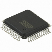
AT32UC3B1128-AUT Atmel, AT32UC3B1128-AUT Datasheet - Page 523

AT32UC3B1128-AUT
Manufacturer Part Number
AT32UC3B1128-AUT
Description
IC MCU AVR32 128KB FLASH 48-TQFP
Manufacturer
Atmel
Series
AVR®32 UC3r
Specifications of AT32UC3B1128-AUT
Core Processor
AVR
Core Size
32-Bit
Speed
60MHz
Connectivity
I²C, IrDA, SPI, SSC, UART/USART, USB
Peripherals
Brown-out Detect/Reset, DMA, POR, PWM, WDT
Number Of I /o
28
Program Memory Size
128KB (128K x 8)
Program Memory Type
FLASH
Ram Size
32K x 8
Voltage - Supply (vcc/vdd)
1.65 V ~ 1.95 V
Data Converters
A/D 6x10b
Oscillator Type
Internal
Operating Temperature
-40°C ~ 85°C
Package / Case
48-TQFP, 48-VQFP
Package
48TQFP
Device Core
AVR32
Family Name
AT32
Maximum Speed
60 MHz
Operating Supply Voltage
1.8|3.3 V
Data Bus Width
32 Bit
Number Of Programmable I/os
28
Interface Type
I2S/SPI/TWI/USART/USB
On-chip Adc
6-chx10-bit
Number Of Timers
3
For Use With
ATSTK600-TQFP48 - STK600 SOCKET/ADAPTER 48-TQFPATAVRONEKIT - KIT AVR/AVR32 DEBUGGER/PROGRMMR770-1008 - ISP 4PORT ATMEL AVR32 MCU SPIATEVK1101 - KIT DEV/EVAL FOR AVR32 AT32UC3B
Lead Free Status / RoHS Status
Lead free / RoHS Compliant
Eeprom Size
-
Available stocks
Company
Part Number
Manufacturer
Quantity
Price
- Current page: 523 of 692
- Download datasheet (11Mb)
24. Pulse Width Modulation Controller (PWM)
24.1
24.2
32059K–03/2011
Features
Description
Rev: 1.3.0.1
•
•
•
•
The PWM macrocell controls several channels independently. Each channel controls one
square output waveform. Characteristics of the output waveform such as period, duty-cycle and
polarity are configurable through the user interface. Each channel selects and uses one of the
clocks provided by the clock generator. The clock generator provides several clocks resulting
from the division of the PWM macrocell master clock.
All PWM macrocell accesses are made through registers mapped on the peripheral bus.
Channels can be synchronized, to generate non overlapped waveforms. All channels integrate a
double buffering system in order to prevent an unexpected output waveform while modifying the
period or the duty-cycle.
7 Channels
One 20-bit Counter Per Channel
Common Clock Generator Providing Thirteen Different Clocks
Independent Channels
– A Modulo n Counter Providing Eleven Clocks
– Two Independent Linear Dividers Working on Modulo n Counter Outputs
– Independent Enable Disable Command for Each Channel
– Independent Clock Selection for Each Channel
– Independent Period and Duty Cycle for Each Channel
– Double Buffering of Period or Duty Cycle for Each Channel
– Programmable Selection of The Output Waveform Polarity for Each Channel
– Programmable Center or Left Aligned Output Waveform for Each Channel
AT32UC3B
523
Related parts for AT32UC3B1128-AUT
Image
Part Number
Description
Manufacturer
Datasheet
Request
R

Part Number:
Description:
DEV KIT FOR AVR/AVR32
Manufacturer:
Atmel
Datasheet:

Part Number:
Description:
INTERVAL AND WIPE/WASH WIPER CONTROL IC WITH DELAY
Manufacturer:
ATMEL Corporation
Datasheet:

Part Number:
Description:
Low-Voltage Voice-Switched IC for Hands-Free Operation
Manufacturer:
ATMEL Corporation
Datasheet:

Part Number:
Description:
MONOLITHIC INTEGRATED FEATUREPHONE CIRCUIT
Manufacturer:
ATMEL Corporation
Datasheet:

Part Number:
Description:
AM-FM Receiver IC U4255BM-M
Manufacturer:
ATMEL Corporation
Datasheet:

Part Number:
Description:
Monolithic Integrated Feature Phone Circuit
Manufacturer:
ATMEL Corporation
Datasheet:

Part Number:
Description:
Multistandard Video-IF and Quasi Parallel Sound Processing
Manufacturer:
ATMEL Corporation
Datasheet:

Part Number:
Description:
High-performance EE PLD
Manufacturer:
ATMEL Corporation
Datasheet:

Part Number:
Description:
8-bit Flash Microcontroller
Manufacturer:
ATMEL Corporation
Datasheet:

Part Number:
Description:
2-Wire Serial EEPROM
Manufacturer:
ATMEL Corporation
Datasheet:


