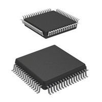
HD64F3664H Renesas Electronics America, HD64F3664H Datasheet - Page 23

HD64F3664H
Manufacturer Part Number
HD64F3664H
Description
IC H8 MCU FLASH 32K 64QFP
Manufacturer
Renesas Electronics America
Series
H8® H8/300H Tinyr
Datasheet
1.US3664-BAG1.pdf
(446 pages)
Specifications of HD64F3664H
Core Processor
H8/300H
Core Size
16-Bit
Speed
16MHz
Connectivity
I²C, SCI
Peripherals
PWM, WDT
Number Of I /o
29
Program Memory Size
32KB (32K x 8)
Program Memory Type
FLASH
Ram Size
2K x 8
Voltage - Supply (vcc/vdd)
3 V ~ 5.5 V
Data Converters
A/D 8x10b
Oscillator Type
External
Operating Temperature
-20°C ~ 75°C
Package / Case
64-QFP
Lead Free Status / RoHS Status
Contains lead / RoHS non-compliant
Eeprom Size
-
Available stocks
Company
Part Number
Manufacturer
Quantity
Price
Company:
Part Number:
HD64F3664H H8/3664
Manufacturer:
RENESAS
Quantity:
13
Company:
Part Number:
HD64F3664HJ
Manufacturer:
TI
Quantity:
171
Part Number:
HD64F3664HJ
Manufacturer:
RENESAS/瑞萨
Quantity:
20 000
Company:
Part Number:
HD64F3664HV
Manufacturer:
ALTERA
Quantity:
101
Company:
Part Number:
HD64F3664HV
Manufacturer:
RENESAS
Quantity:
630
Company:
Part Number:
HD64F3664HV
Manufacturer:
Renesas Electronics America
Quantity:
10 000
Part Number:
HD64F3664HV
Manufacturer:
RENESAS/瑞萨
Quantity:
20 000
- Current page: 23 of 446
- Download datasheet (3Mb)
Figure 11.2 Increment Timing with Internal Clock .................................................................... 153
Figure 11.3 Increment Timing with External Clock ................................................................... 153
Figure 11.4 OVF Set Timing ...................................................................................................... 153
Figure 11.5 CMFA and CMFB Set Timing ................................................................................ 154
Figure 11.6 TMOV Output Timing ............................................................................................ 154
Figure 11.7 Clear Timing by Compare Match............................................................................ 154
Figure 11.8 Clear Timing by TMRIV Input ............................................................................... 155
Figure 11.9 Pulse Output Example ............................................................................................. 155
Figure 11.10 Example of Pulse Output Synchronized to TRGV Input....................................... 156
Figure 11.11 Contention between TCNTV Write and Clear ...................................................... 157
Figure 11.12 Contention between TCORA Write and Compare Match ..................................... 158
Figure 11.13 Internal Clock Switching and TCNTV Operation ................................................. 158
Section 12 Timer W
Figure 12.1 Timer W Block Diagram ......................................................................................... 161
Figure 12.2 Free-Running Counter Operation ............................................................................ 172
Figure 12.3 Periodic Counter Operation..................................................................................... 173
Figure 12.4 0 and 1 Output Example (TOA = 0, TOB = 1)........................................................ 173
Figure 12.5 Toggle Output Example (TOA = 0, TOB = 1) ........................................................ 174
Figure 12.6 Toggle Output Example (TOA = 0, TOB = 1) ........................................................ 174
Figure 12.7 Input Capture Operating Example........................................................................... 175
Figure 12.8 Buffer Operation Example (Input Capture)............................................................. 176
Figure 12.9 PWM Mode Example (1) ........................................................................................ 177
Figure 12.10 PWM Mode Example (2) ...................................................................................... 177
Figure 12.11 Buffer Operation Example (Output Compare) ...................................................... 178
Figure 12.12 PWM Mode Example
Figure 12.13 PWM Mode Example
Figure 12.14 Count Timing for Internal Clock Source ............................................................... 181
Figure 12.15 Count Timing for External Clock Source.............................................................. 181
Figure 12.16 Output Compare Output Timing ........................................................................... 182
Figure 12.17 Input Capture Input Signal Timing........................................................................ 183
Figure 12.18 Timing of Counter Clearing by Compare Match................................................... 183
Figure 12.19 Buffer Operation Timing (Compare Match).......................................................... 184
Figure 12.20 Buffer Operation Timing (Input Capture) ............................................................. 184
Figure 12.21 Timing of IMFA to IMFD Flag Setting at Compare Match .................................. 185
Figure 12.22 Timing of IMFA to IMFD Flag Setting at Input Capture...................................... 186
Figure 12.23 Timing of Status Flag Clearing by CPU................................................................ 186
Figure 12.24 Contention between TCNT Write and Clear ......................................................... 187
Figure 12.25 Internal Clock Switching and TCNT Operation.................................................... 188
(TOB, TOC, and TOD = 0: initial output values are set to 0)............................... 179
(TOB, TOC, and TOD = 1: initial output values are set to 1)............................... 180
Rev. 6.00 Mar. 24, 2006 Page xxi of xxviii
Related parts for HD64F3664H
Image
Part Number
Description
Manufacturer
Datasheet
Request
R

Part Number:
Description:
(HD64 Series) Hitachi Single-Chip Microcomputer
Manufacturer:
Hitachi Semiconductor
Datasheet:

Part Number:
Description:
KIT STARTER FOR M16C/29
Manufacturer:
Renesas Electronics America
Datasheet:

Part Number:
Description:
KIT STARTER FOR R8C/2D
Manufacturer:
Renesas Electronics America
Datasheet:

Part Number:
Description:
R0K33062P STARTER KIT
Manufacturer:
Renesas Electronics America
Datasheet:

Part Number:
Description:
KIT STARTER FOR R8C/23 E8A
Manufacturer:
Renesas Electronics America
Datasheet:

Part Number:
Description:
KIT STARTER FOR R8C/25
Manufacturer:
Renesas Electronics America
Datasheet:

Part Number:
Description:
KIT STARTER H8S2456 SHARPE DSPLY
Manufacturer:
Renesas Electronics America
Datasheet:

Part Number:
Description:
KIT STARTER FOR R8C38C
Manufacturer:
Renesas Electronics America
Datasheet:

Part Number:
Description:
KIT STARTER FOR R8C35C
Manufacturer:
Renesas Electronics America
Datasheet:

Part Number:
Description:
KIT STARTER FOR R8CL3AC+LCD APPS
Manufacturer:
Renesas Electronics America
Datasheet:

Part Number:
Description:
KIT STARTER FOR RX610
Manufacturer:
Renesas Electronics America
Datasheet:

Part Number:
Description:
KIT STARTER FOR R32C/118
Manufacturer:
Renesas Electronics America
Datasheet:

Part Number:
Description:
KIT DEV RSK-R8C/26-29
Manufacturer:
Renesas Electronics America
Datasheet:

Part Number:
Description:
KIT STARTER FOR SH7124
Manufacturer:
Renesas Electronics America
Datasheet:

Part Number:
Description:
KIT STARTER FOR H8SX/1622
Manufacturer:
Renesas Electronics America
Datasheet:


