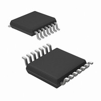
MRF49XA-I/ST Microchip Technology, MRF49XA-I/ST Datasheet - Page 57

MRF49XA-I/ST
Manufacturer Part Number
MRF49XA-I/ST
Description
IC RF TXRX 433/868/915 16-TSSOP
Manufacturer
Microchip Technology
Datasheet
1.MRF49XA-IST.pdf
(102 pages)
Specifications of MRF49XA-I/ST
Package / Case
16-TSSOP
Frequency
433MHz, 868MHz, 915MHz
Data Rate - Maximum
256kbps
Modulation Or Protocol
FHSS, FSK
Applications
Home / Industrial Automation, Remote Access, Security Alarms
Power - Output
7dbm
Sensitivity
-110dBm
Voltage - Supply
2.2 V ~ 3.8 V
Current - Receiving
11mA
Current - Transmitting
15mA
Data Interface
PCB, Surface Mount
Antenna Connector
PCB, Surface Mount
Operating Temperature
-40°C ~ 85°C
Number Of Receivers
1
Number Of Transmitters
2
Wireless Frequency
433 MHz to 915 MHz
Output Power
+ 7 dBm
Operating Supply Voltage
2.5 V, 3.3 V
Maximum Operating Temperature
+ 85 C
Mounting Style
SMD/SMT
Minimum Operating Temperature
- 40 C
Modulation
FHSS, FSK
Lead Free Status / RoHS Status
Lead free / RoHS Compliant
Memory Size
-
Lead Free Status / Rohs Status
Lead free / RoHS Compliant
Other names
579-MRF49XA-1/ST
Available stocks
Company
Part Number
Manufacturer
Quantity
Price
Company:
Part Number:
MRF49XA-I/ST
Manufacturer:
IR
Quantity:
450
Part Number:
MRF49XA-I/ST
Manufacturer:
MICROCHIP/微芯
Quantity:
20 000
FIGURE 3-9:
The baseband filtering type can also be selected
between an analog filter and a digital filter.
3.10.1
For analog filtering, a simple RC low-pass filter is used,
along with a Schmitt Trigger circuit. The demodulator
output is fed to the RCLKOUT/FCAP/FINT pin over a
10 kΩ resistor. The filter cut-off frequency is set by the
external capacitor connected to this pin and V
10 kΩ resistor and the Schmitt Trigger are integrated
on the chip. An external capacitor for the RC filter has
to be chosen in accordance with the required bit rate.
The receiver can handle up to 256 kbps of data rate in
analog operation. The receive data rate is program-
mable from 337 bps to 256 kbps. An internal prescaler
can be used to give better resolution when setting up
the receive data rate. The prescaler is optional and can
be disabled through DRSREG. The analog filtering
does not use the FIFO and the clock. The clock is not
provided for the demodulated data, and hence, there is
no need for setting the correct bit rate.
© 2009 Microchip Technology Inc.
Programmable
BBBW
ANALOG FILTERING MODE
10 kHz + Data Rate
FSK MODULATED DEVIATION – MAXIMUM TX TO RX OFFSET
10 kHz
SS
Preliminary
. A
Amplitude
Baseband Filter Characteristic
2 x deviation
3.10.2
A digital filter is used with a clock frequency at 29 times
the data rate. For digital filtering, the synchronized
clock to the data is provided by the clock recovery
circuit. By using this clock, the received data can fill the
FIFO. If the FIFO is not used, the recovered clock can
be accessed through RCLKOUT/FCAP/ FINT pin.
The clock recovery circuit operates in three modes:
Automatic mode, Slow mode and Fast mode. All three
modes are configurable through BBFCREG. Each
mode is dependent on the type of signals it uses to
determine the valid data and also the number of incom-
ing preamble bits present at the beginning of the
packet. In Automatic mode, the CR clock recovery
circuit automatically switches between the Fast and
Slow mode. The noise immunity of the clock recovery
circuit is very high in Slow mode; however, it has slower
settling time and requires more accurate data timing
than in Fast mode.
The registers associated with baseband filtering are:
• STSREG (see Register 2-1)
• RXCREG (see Register 2-7)
• BBFCREG (see Register 2-8)
• PMCREG (see Register 2-13)
RX Center
Freq.
DIGITAL FILTERING MODE
TX-RX Offset
Data Rate
TX Center
Freq.
MRF49XA
DS70590B-page 55
Frequency


