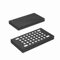
ATMEGA16HVA-4CKU Atmel, ATMEGA16HVA-4CKU Datasheet - Page 107

ATMEGA16HVA-4CKU
Manufacturer Part Number
ATMEGA16HVA-4CKU
Description
MCU AVR 16K FLASH 4MHZ 36-LGA
Manufacturer
Atmel
Series
AVR® ATmegar
Datasheet
1.ATMEGA16HVA-4CKU.pdf
(196 pages)
Specifications of ATMEGA16HVA-4CKU
Core Processor
AVR
Core Size
8-Bit
Speed
4MHz
Connectivity
SPI
Peripherals
Brown-out Detect/Reset, POR, PWM, WDT
Number Of I /o
7
Program Memory Size
16KB (8K x 16)
Program Memory Type
FLASH
Eeprom Size
256 x 8
Ram Size
512 x 8
Voltage - Supply (vcc/vdd)
1.8 V ~ 9 V
Data Converters
A/D 5x12b
Oscillator Type
External
Operating Temperature
-20°C ~ 85°C
Package / Case
36-LGA
Processor Series
ATMEGA16x
Core
AVR8
Data Bus Width
8 bit
Data Ram Size
512 B
Interface Type
SPI
Maximum Clock Frequency
4 MHz
Number Of Programmable I/os
6
Number Of Timers
2
Maximum Operating Temperature
+ 85 C
Mounting Style
SMD/SMT
3rd Party Development Tools
EWAVR, EWAVR-BL
Development Tools By Supplier
ATAVRDRAGON, ATSTK500, ATSTK600, ATAVRISP2, ATAVRONEKIT, ATAVRSB200, ATAVRSB201
Minimum Operating Temperature
- 20 C
On-chip Adc
12 bit, 5 Channel
For Use With
ATSTK600 - DEV KIT FOR AVR/AVR32ATSTK500 - PROGRAMMER AVR STARTER KIT
Lead Free Status / RoHS Status
Lead free / RoHS Compliant
- Current page: 107 of 196
- Download datasheet (3Mb)
19.5
19.6
19.7
19.7.1
8024A–AVR–04/08
Offset Canceling by Polarity Switching
Configuration and Usage
Register Description
CADCSRA - CC-ADC Control and Status Register A
Instantaneous Current Interrupt should be enabled as wake-up source by setting the CADICIE
bit. The device will then wake-up from sleep after each single IC measurement. To check if Reg-
ular Current Detection has occurred the Regular Current Detection flag, CADRCIF, should be
read.
The CC-ADC offers Polarity Switching for internal offset canceling. By switching the polarity of
the sampled input signal at selected time intervals, the internal voltage offset of the CC-ADC will
cancel at the output. This feature prevents the CC-ADC from accumulating an offset error over
time.
While the CC-ADC is converting, the CPU can enter sleep mode and wait for an interrupt. After
adding the conversion data for the Coulomb Counting, the CPU can go back to sleep again. This
reduces the CPU workload, and allows more time spent in low power modes, reducing power
consumption.
To use the CC-ADC, the bandgap voltage reference must be enabled. See
and Temperature Sensor” on page
The CC-ADC will not consume power when CADEN is cleared. It is therefore recommended to
switch off the CC-ADC whenever the Coulomb Counter or Regular Current Detection functions
are not used. The CC-ADC is automatically disabled in Power-off mode.
After the CC-ADC is enabled by setting the CADEN bit, the first three Instantaneous conversions
do not contain useful data and should be ignored. This also applies after clearing the CADSE bit,
or after changing the CADPOL or CADVSE bits.
The conversion times and sampling intervals are controlled by the Slow RC Oscillator, and will
depend on its actual frequency. To obtain accurate coulomb counting results, the actual conver-
sion time must be calculated. Refer to
• Bit 7 - CADEN: CC-ADC Enable
When the CADEN bit is cleared (zero), the CC-ADC is disabled, and any ongoing conversions
will be terminated. When the CADEN bit is set (one), the CC-ADC will continuously measure the
voltage drop over the external sense resistor R
abled. Note that the bandgap voltage reference must be enabled, see
Temperature Sensor” on page
• Bit 6 - CADPOL: CC-ADC Polarity
The CADPOL bit is used to change input sampling polarity in the Sigma Delta Modulator. Writing
this bit to one, the polarity will be negative. When the bit is zero, the polarity will be positive.
Bit
(0xE4)
Read/Write
Initial Value
CADEN
R/W
7
0
CADPOL
R/W
6
0
117.
CADUB
R
5
0
117.
”Slow RC Oscillator” on page 26
CADAS1
R/W
4
0
SENSE
CADAS0
R/W
3
0
. In Power-off, the CC-ADC is always dis-
ATmega8HVA/16HVA
CADSI1
R/W
2
0
CADSI0
R/W
1
0
for details.
”Voltage Reference and
”Voltage Reference
CADSE
R/W
0
0
CADCSRA
107
Related parts for ATMEGA16HVA-4CKU
Image
Part Number
Description
Manufacturer
Datasheet
Request
R

Part Number:
Description:
DEV KIT FOR AVR/AVR32
Manufacturer:
Atmel
Datasheet:

Part Number:
Description:
INTERVAL AND WIPE/WASH WIPER CONTROL IC WITH DELAY
Manufacturer:
ATMEL Corporation
Datasheet:

Part Number:
Description:
Low-Voltage Voice-Switched IC for Hands-Free Operation
Manufacturer:
ATMEL Corporation
Datasheet:

Part Number:
Description:
MONOLITHIC INTEGRATED FEATUREPHONE CIRCUIT
Manufacturer:
ATMEL Corporation
Datasheet:

Part Number:
Description:
AM-FM Receiver IC U4255BM-M
Manufacturer:
ATMEL Corporation
Datasheet:

Part Number:
Description:
Monolithic Integrated Feature Phone Circuit
Manufacturer:
ATMEL Corporation
Datasheet:

Part Number:
Description:
Multistandard Video-IF and Quasi Parallel Sound Processing
Manufacturer:
ATMEL Corporation
Datasheet:

Part Number:
Description:
High-performance EE PLD
Manufacturer:
ATMEL Corporation
Datasheet:

Part Number:
Description:
8-bit Flash Microcontroller
Manufacturer:
ATMEL Corporation
Datasheet:

Part Number:
Description:
2-Wire Serial EEPROM
Manufacturer:
ATMEL Corporation
Datasheet:


