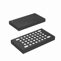
ATMEGA16HVA-4CKU Atmel, ATMEGA16HVA-4CKU Datasheet - Page 125

ATMEGA16HVA-4CKU
Manufacturer Part Number
ATMEGA16HVA-4CKU
Description
MCU AVR 16K FLASH 4MHZ 36-LGA
Manufacturer
Atmel
Series
AVR® ATmegar
Datasheet
1.ATMEGA16HVA-4CKU.pdf
(196 pages)
Specifications of ATMEGA16HVA-4CKU
Core Processor
AVR
Core Size
8-Bit
Speed
4MHz
Connectivity
SPI
Peripherals
Brown-out Detect/Reset, POR, PWM, WDT
Number Of I /o
7
Program Memory Size
16KB (8K x 16)
Program Memory Type
FLASH
Eeprom Size
256 x 8
Ram Size
512 x 8
Voltage - Supply (vcc/vdd)
1.8 V ~ 9 V
Data Converters
A/D 5x12b
Oscillator Type
External
Operating Temperature
-20°C ~ 85°C
Package / Case
36-LGA
Processor Series
ATMEGA16x
Core
AVR8
Data Bus Width
8 bit
Data Ram Size
512 B
Interface Type
SPI
Maximum Clock Frequency
4 MHz
Number Of Programmable I/os
6
Number Of Timers
2
Maximum Operating Temperature
+ 85 C
Mounting Style
SMD/SMT
3rd Party Development Tools
EWAVR, EWAVR-BL
Development Tools By Supplier
ATAVRDRAGON, ATSTK500, ATSTK600, ATAVRISP2, ATAVRONEKIT, ATAVRSB200, ATAVRSB201
Minimum Operating Temperature
- 20 C
On-chip Adc
12 bit, 5 Channel
For Use With
ATSTK600 - DEV KIT FOR AVR/AVR32ATSTK500 - PROGRAMMER AVR STARTER KIT
Lead Free Status / RoHS Status
Lead free / RoHS Compliant
- Current page: 125 of 196
- Download datasheet (3Mb)
23.3
23.4
23.5
23.6
8024A–AVR–04/08
Short-circuit Protection
Discharge Over-current Protection
Charge Over-current Protection
Discharge High-current Protection
The Current Battery Protection (CBP) monitors the cell current by sampling the shunt resistor
voltage at the PI/NI input pins. A differential operational amplifier amplifies the voltage with a
suitable gain. The output from the operational amplifier is compared to an accurate, programma-
ble On-chip voltage reference by an Analog Comparator. If the shunt resistor voltage is above
the Detection level for a time longer than the corresponding Protection Reaction Time, the chip
activates Current Protection. A sampled system clocked by the internal ULP Oscillator is used
for Short-circuit, Over-current, and High-current Protection. This ensures a reliable clock source,
offset cancellation and low power consumption.
The Short-circuit detection is provided to enable a fast response time to very large discharge
currents. If the voltage at the PI/NI pins is above the Short-circuit Detection Level for a period
longer than Short-circuit Reaction Time, the Short-circuit Protection is activated.
When the Short-circuit Protection is activated, the external D-FET and C-FET are disabled and a
Current Protection Timer is started. This timer ensures that the D-FET and C-FET are disabled
for at least one second. The application software must then set the DFE and CFE bits in the FET
Control and Status Register to re-enable normal operation. If the D-FET is re-enabled before the
cause of the short-circuit condition is removed, the Short-circuit Protection will be activated
again.
If the voltage at the PI/NI pins is above the Discharge Over-current Detection level for a time
longer than Over-current Protection Reaction Time, the chip activates Discharge Over-current
Protection.
When the Discharge Over-current Protection is activated, the external D-FET and C-FET are
disabled and a Current Protection Timer is started. This timer ensures that the FETs are dis-
abled for at least one second. The application software must then set the DFE and CFE bits in
the FET Control and Status Register to re-enable normal operation. If the D-FET is re-enabled
while the loading of the battery still is too large, the Discharge Over-current Protection will be
activated again.
If the voltage at the PI/NI pins is above the Charge Over-current Detection level for a time longer
than Over-current Protection Reaction Time, the chip activates Charge Over-current Protection.
When the Charge Over-current Protection is activated, the external D-FET and C-FET are dis-
abled and a Current Protection Timer is started. This timer ensures that the FETs are disabled
for at least one second. The application software must then set the DFE and CFE bits in the FET
Control and Status Register to re-enable normal operation. If the C-FET is re-enabled and the
charger continues to supply too high currents, the Charge Over-current Protection will be acti-
vated again.
If the voltage at the PI/NI pins is above the Discharge High-current Detection level for a time
longer than High-current Protection Reaction Time, the chip activates Discharge High-current
Protection.
ATmega8HVA/16HVA
125
Related parts for ATMEGA16HVA-4CKU
Image
Part Number
Description
Manufacturer
Datasheet
Request
R

Part Number:
Description:
DEV KIT FOR AVR/AVR32
Manufacturer:
Atmel
Datasheet:

Part Number:
Description:
INTERVAL AND WIPE/WASH WIPER CONTROL IC WITH DELAY
Manufacturer:
ATMEL Corporation
Datasheet:

Part Number:
Description:
Low-Voltage Voice-Switched IC for Hands-Free Operation
Manufacturer:
ATMEL Corporation
Datasheet:

Part Number:
Description:
MONOLITHIC INTEGRATED FEATUREPHONE CIRCUIT
Manufacturer:
ATMEL Corporation
Datasheet:

Part Number:
Description:
AM-FM Receiver IC U4255BM-M
Manufacturer:
ATMEL Corporation
Datasheet:

Part Number:
Description:
Monolithic Integrated Feature Phone Circuit
Manufacturer:
ATMEL Corporation
Datasheet:

Part Number:
Description:
Multistandard Video-IF and Quasi Parallel Sound Processing
Manufacturer:
ATMEL Corporation
Datasheet:

Part Number:
Description:
High-performance EE PLD
Manufacturer:
ATMEL Corporation
Datasheet:

Part Number:
Description:
8-bit Flash Microcontroller
Manufacturer:
ATMEL Corporation
Datasheet:

Part Number:
Description:
2-Wire Serial EEPROM
Manufacturer:
ATMEL Corporation
Datasheet:


