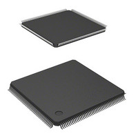
HD6417706F133 Renesas Electronics America, HD6417706F133 Datasheet - Page 62

HD6417706F133
Manufacturer Part Number
HD6417706F133
Description
IC SUPERH MPU ROMLESS 176LQFP
Manufacturer
Renesas Electronics America
Series
SuperH® SH7700r
Datasheet
1.HD6417706F133V.pdf
(751 pages)
Specifications of HD6417706F133
Core Processor
SH-3
Core Size
32-Bit
Speed
133MHz
Connectivity
EBI/EMI, FIFO, SCI, SmartCard
Peripherals
DMA, POR, WDT
Number Of I /o
103
Program Memory Type
ROMless
Ram Size
16K x 8
Voltage - Supply (vcc/vdd)
1.75 V ~ 2.05 V
Oscillator Type
Internal
Operating Temperature
-20°C ~ 75°C
Package / Case
176-LQFP
Lead Free Status / RoHS Status
Contains lead / RoHS non-compliant
Eeprom Size
-
Program Memory Size
-
Data Converters
-
Available stocks
Company
Part Number
Manufacturer
Quantity
Price
Part Number:
HD6417706F133
Manufacturer:
RENESAS/瑞萨
Quantity:
20 000
Company:
Part Number:
HD6417706F133V
Manufacturer:
EDISON
Quantity:
2 000
Company:
Part Number:
HD6417706F133V
Manufacturer:
Renesas Electronics America
Quantity:
10 000
Part Number:
HD6417706F133V
Manufacturer:
RENESAS/瑞萨
Quantity:
20 000
- Current page: 62 of 751
- Download datasheet (5Mb)
Section 1 Overview
Number of Pins
FP-176C
157
158
159
160
161
162
163
164
165
166
167
168
169
170
171
172
173
174
175
176
Notes: Except in hardware standby mode, all V
Rev. 5.00 May 29, 2006 page 12 of 698
REJ09B0146-0500
supply. (Supply power constantly.) In hardware standby mode, power must be supplied at
least to V
V
In the TBP-208A package, the A1, A2, A3, A7, A12, B1, C4, C7, D1, D2, D4, D7, D14, D15,
E1, E2, E3, E4, F14, F17, G17, H14, H15, K14, P14, R10, T13, T15, T16, U11, U15, and
U16 pins must be connected to V
1. Must be connected to the power supply even when the RTC is not used.
2. Must be connected to the power supply even when the on-chip PLL circuits are not
3. Must be high level when the user system is used independently without using the
CC
used (except in hardware standby mode).
emulator or H-UDI. When this pin goes low or is open, the RESETP pin may be
masked. (See section 21, User Debugging Interface (H-UDI).)
TBP-208A
B9
A9
C9
A8
B8
C8
D8
B7
A6
B6
C6
D6
A5
B5
C5
D5
A4
B4
B3
B2
RTC and V
CC
RTC and V
SS
Pin Name
NMI
V
AUDCK/PTG[4]
DREQ0/PTH[5]
DREQ1/PTH[6]
ADTRG/PTG[5]
MD0
MD2
RESETP
CA
MD3
MD4
MD5
AV
AN[0]/PTJ[0]
AN[1]/PTJ[1]
AN[2]/DA[1]/PTJ[2]
AN[3]/DA[0]/PTJ[3]
AV
AV
RTC, hold the CA pin low.
CC
SS
CC
SS
Q
SS
RTC. If power is not supplied to V
SS
.
CC
/V
SS
I/O
I
—
I
I / I/O
I / I/O
I
I
I
I
I
I
I
I
—
I
I
I / O / I
I / O / I
—
—
pins must be connected to the system power
Description
Nonmaskable interrupt request
Input/output power supply (3.3 V)
AUD clock / input port G
DMA request / input/output port H
DMA request / input/output port H
Analog trigger / input port G
Clock mode setting
Clock mode setting
Power-on reset request
Chip activate / hardware standby
request
Area 0 bus width setting
Area 0 bus width setting
Endian setting
Analog power supply (0 V)
A/D converter input / input port J
A/D converter input / input port J
output / input port J
output / input port J
Analog power supply (3.3 V)
Analog power supply (0 V)
A/D converter input / D/A converter
A/D converter input / D/A converter
CC
and V
SS
pins other than
Related parts for HD6417706F133
Image
Part Number
Description
Manufacturer
Datasheet
Request
R

Part Number:
Description:
KIT STARTER FOR M16C/29
Manufacturer:
Renesas Electronics America
Datasheet:

Part Number:
Description:
KIT STARTER FOR R8C/2D
Manufacturer:
Renesas Electronics America
Datasheet:

Part Number:
Description:
R0K33062P STARTER KIT
Manufacturer:
Renesas Electronics America
Datasheet:

Part Number:
Description:
KIT STARTER FOR R8C/23 E8A
Manufacturer:
Renesas Electronics America
Datasheet:

Part Number:
Description:
KIT STARTER FOR R8C/25
Manufacturer:
Renesas Electronics America
Datasheet:

Part Number:
Description:
KIT STARTER H8S2456 SHARPE DSPLY
Manufacturer:
Renesas Electronics America
Datasheet:

Part Number:
Description:
KIT STARTER FOR R8C38C
Manufacturer:
Renesas Electronics America
Datasheet:

Part Number:
Description:
KIT STARTER FOR R8C35C
Manufacturer:
Renesas Electronics America
Datasheet:

Part Number:
Description:
KIT STARTER FOR R8CL3AC+LCD APPS
Manufacturer:
Renesas Electronics America
Datasheet:

Part Number:
Description:
KIT STARTER FOR RX610
Manufacturer:
Renesas Electronics America
Datasheet:

Part Number:
Description:
KIT STARTER FOR R32C/118
Manufacturer:
Renesas Electronics America
Datasheet:

Part Number:
Description:
KIT DEV RSK-R8C/26-29
Manufacturer:
Renesas Electronics America
Datasheet:

Part Number:
Description:
KIT STARTER FOR SH7124
Manufacturer:
Renesas Electronics America
Datasheet:

Part Number:
Description:
KIT STARTER FOR H8SX/1622
Manufacturer:
Renesas Electronics America
Datasheet:

Part Number:
Description:
KIT DEV FOR SH7203
Manufacturer:
Renesas Electronics America
Datasheet:


