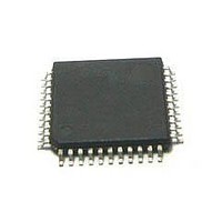
MC56F8245VLD Freescale Semiconductor, MC56F8245VLD Datasheet - Page 163

MC56F8245VLD
Manufacturer Part Number
MC56F8245VLD
Description
DSC 48K FLASH 60MHZ 44-LQFP
Manufacturer
Freescale Semiconductor
Series
56F8xxxr
Datasheets
1.TWR-56F8257.pdf
(88 pages)
2.MC56F8245VLD.pdf
(14 pages)
3.MC56F8245VLD.pdf
(2 pages)
4.MC56F8245VLD.pdf
(629 pages)
Specifications of MC56F8245VLD
Core Processor
56800E
Core Size
16-Bit
Speed
60MHz
Connectivity
CAN, I²C, LIN, SCI, SPI
Peripherals
LVD, POR, PWM, WDT
Number Of I /o
35
Program Memory Size
48KB (24K x 16)
Program Memory Type
FLASH
Ram Size
3K x 16
Voltage - Supply (vcc/vdd)
3 V ~ 3.6 V
Data Converters
A/D 8x12b, D/A 1x12b
Oscillator Type
Internal
Operating Temperature
-40°C ~ 105°C
Package / Case
44-LQFP
Product
DSCs
Processor Series
56800E
Core
56800E
Device Million Instructions Per Second
60 MIPs
Maximum Clock Frequency
60 MHz
Number Of Programmable I/os
35
Data Ram Size
6 KB
Operating Supply Voltage
3.3 V
Maximum Operating Temperature
+ 105 C
Mounting Style
SMD/SMT
Minimum Operating Temperature
- 40 C
On-chip Adc
12 bit, 4 Channel
Package
44LQFP
Family Name
MC56F82xx
Maximum Speed
60 MHz
Data Bus Width
16 Bit
Interface Type
I2C/SCI/SPI
On-chip Dac
1-chx12-bit
Number Of Timers
8
Lead Free Status / RoHS Status
Lead free / RoHS Compliant
Eeprom Size
-
Lead Free Status / Rohs Status
Details
Available stocks
Company
Part Number
Manufacturer
Quantity
Price
Company:
Part Number:
MC56F8245VLD
Manufacturer:
FREESCAL
Quantity:
269
Company:
Part Number:
MC56F8245VLD
Manufacturer:
Freescale Semiconductor
Quantity:
10 000
- TWR-56F8257 PDF datasheet
- MC56F8245VLD PDF datasheet #2
- MC56F8245VLD PDF datasheet #3
- MC56F8245VLD PDF datasheet #4
- Current page: 163 of 629
- Download datasheet (4Mb)
6.5.12 Timer Channel Input Filter Register (TMRx_FILT)
Input filter considerations:
Freescale Semiconductor
• Set the FILT_PER value such that the sampling period is larger than the period of the
• The values of FILT_PER and FILT_CNT must also be balanced against the desire
TCF2EN
TCF1EN
expected noise. In this way, a noise spike will corrupt only one sample. Choose the
FILT_CNT value to reduce the probability that noisy samples cause an incorrect
transition to be recognized. The probability of an incorrect transistion is defined as
the probability of an incorrect sample raised to the power of (FILT_CNT + 3).
for minimal latency in recognizing input transitions. Turning on the input filter
(setting FILT_PER to a non-zero value) introduces a latency of (((FILT_CNT + 3) x
FILT_PER) + 2) IP bus clock periods.
TCF2
TCF1
Field
CL2
CL1
3–2
1–0
7
6
5
4
Timer Compare 2 Interrupt Enable
An interrupt is issued when both this bit and TCF2 are set.
Timer Compare 1 Interrupt Enable
An interrupt is issued when both this bit and TCF1 are set.
Timer Compare 2 Interrupt Flag
When set, this bit indicates a successful comparison of the timer and the the COMP2 register has
occurred. This bit is sticky, and will remain set until explicitly cleared by writing a zero to this bit location.
Timer Compare 1 Interrupt Flag
When set, this bit indicates a successful comparison of the timer and the the COMP1 register has
occurred. This bit is sticky, and will remain set until explicitly cleared by writing a zero to this bit location.
Compare Load Control 2
These bits control when COMP2 is preloaded with the value from CMPLD2.
00
01
10
11
Compare Load Control 1
These bits control when COMP1 is preloaded with the value from CMPLD1.
00
01
10
11
Never preload
Load upon successful compare with the value in COMP1
Load upon successful compare with the value in COMP2
Reserved
Never preload
Load upon successful compare with the value in COMP1
Load upon successful compare with the value in COMP2
Reserved
TMRx_CSCTRL field descriptions (continued)
MC56F825x/4x Reference Manual, Rev. 2, 10/2010
Preliminary
Description
Chapter 6 Quad Timer (TMR)
163
Related parts for MC56F8245VLD
Image
Part Number
Description
Manufacturer
Datasheet
Request
R
Part Number:
Description:
Manufacturer:
Freescale Semiconductor, Inc
Datasheet:
Part Number:
Description:
Manufacturer:
Freescale Semiconductor, Inc
Datasheet:
Part Number:
Description:
Manufacturer:
Freescale Semiconductor, Inc
Datasheet:
Part Number:
Description:
Manufacturer:
Freescale Semiconductor, Inc
Datasheet:
Part Number:
Description:
Manufacturer:
Freescale Semiconductor, Inc
Datasheet:
Part Number:
Description:
Manufacturer:
Freescale Semiconductor, Inc
Datasheet:
Part Number:
Description:
Manufacturer:
Freescale Semiconductor, Inc
Datasheet:
Part Number:
Description:
Manufacturer:
Freescale Semiconductor, Inc
Datasheet:
Part Number:
Description:
Manufacturer:
Freescale Semiconductor, Inc
Datasheet:
Part Number:
Description:
Manufacturer:
Freescale Semiconductor, Inc
Datasheet:
Part Number:
Description:
Manufacturer:
Freescale Semiconductor, Inc
Datasheet:
Part Number:
Description:
Manufacturer:
Freescale Semiconductor, Inc
Datasheet:
Part Number:
Description:
Manufacturer:
Freescale Semiconductor, Inc
Datasheet:
Part Number:
Description:
Manufacturer:
Freescale Semiconductor, Inc
Datasheet:
Part Number:
Description:
Manufacturer:
Freescale Semiconductor, Inc
Datasheet:


