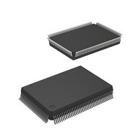
DF2367VF33 Renesas Electronics America, DF2367VF33 Datasheet - Page 55

DF2367VF33
Manufacturer Part Number
DF2367VF33
Description
MCU 3V 384K 128-QFP
Manufacturer
Renesas Electronics America
Series
H8® H8S/2300r
Datasheet
1.DF2368VTE34V.pdf
(1044 pages)
Specifications of DF2367VF33
Core Processor
H8S/2000
Core Size
16-Bit
Speed
33MHz
Connectivity
I²C, IrDA, SCI, SmartCard
Peripherals
DMA, POR, PWM, WDT
Number Of I /o
84
Program Memory Size
384KB (384K x 8)
Program Memory Type
FLASH
Ram Size
24K x 8
Voltage - Supply (vcc/vdd)
3 V ~ 3.6 V
Data Converters
A/D 10x10b, D/A 2x8b
Oscillator Type
Internal
Operating Temperature
-20°C ~ 75°C
Package / Case
128-QFP
Lead Free Status / RoHS Status
Contains lead / RoHS non-compliant
Eeprom Size
-
Other names
HD64F2367VF33
HD64F2367VF33
HD64F2367VF33
Available stocks
Company
Part Number
Manufacturer
Quantity
Price
Company:
Part Number:
DF2367VF33V
Manufacturer:
Renesas Electronics America
Quantity:
135
Company:
Part Number:
DF2367VF33V
Manufacturer:
Renesas Electronics America
Quantity:
10 000
Company:
Part Number:
DF2367VF33WV
Manufacturer:
Renesas Electronics America
Quantity:
10 000
- Current page: 55 of 1044
- Download datasheet (6Mb)
Table 9.6
Section 10 16-Bit Timer Pulse Unit (TPU)
Table 10.1
Table 10.2
Table 10.3
Table 10.4
Table 10.5
Table 10.6
Table 10.7
Table 10.8
Table 10.9
Table 10.10 TPSC2 to TPSC0 (Channel 5)................................................................................ 412
Table 10.11 MD3 to MD0.......................................................................................................... 414
Table 10.12 TIORH_0................................................................................................................ 416
Table 10.13 TIORL_0 ................................................................................................................ 417
Table 10.14 TIOR_1 .................................................................................................................. 418
Table 10.15 TIOR_2 .................................................................................................................. 419
Table 10.16 TIORH_3................................................................................................................ 420
Table 10.17 TIORL_3 ................................................................................................................ 421
Table 10.18 TIOR_4 .................................................................................................................. 422
Table 10.19 TIOR_5 .................................................................................................................. 423
Table 10.20 TIORH_0................................................................................................................ 424
Table 10.21 TIORL_0 ................................................................................................................ 425
Table 10.22 TIOR_1 .................................................................................................................. 426
Table 10.23 TIOR_2 .................................................................................................................. 427
Table 10.24 TIORH_3................................................................................................................ 428
Table 10.25 TIORL_3 ................................................................................................................ 429
Table 10.26 TIOR_4 .................................................................................................................. 430
Table 10.27 TIOR_5 .................................................................................................................. 431
Table 10.28 Register Combinations in Buffer Operation........................................................... 448
Table 10.29 Cascaded Combinations ......................................................................................... 452
Table 10.30 PWM Output Registers and Output Pins................................................................ 455
Table 10.31 Clock Input Pins in Phase Counting Mode............................................................. 459
Table 10.32 Up/Down-Count Conditions in Phase Counting Mode 1 ....................................... 461
Table 10.33 Up/Down-Count Conditions in Phase Counting Mode 2 ....................................... 462
Table 10.34 Up/Down-Count Conditions in Phase Counting Mode 3 ...................................... 463
Table 10.35 Up/Down-Count Conditions in Phase Counting Mode 4 ....................................... 464
Table 10.36 TPU Interrupts........................................................................................................ 467
MOS Input Pull-Up States (Port E) ........................................................................ 388
TPU Functions........................................................................................................ 402
Pin Configuration ................................................................................................... 405
CCLR2 to CCLR0 (Channels 0 and 3)................................................................... 409
CCLR2 to CCLR0 (Channels 1, 2, 4, and 5).......................................................... 409
TPSC2 to TPSC0 (Channel 0)................................................................................ 410
TPSC2 to TPSC0 (Channel 1)................................................................................ 410
TPSC2 to TPSC0 (Channel 2)................................................................................ 411
TPSC2 to TPSC0 (Channel 3)................................................................................ 411
TPSC2 to TPSC0 (Channel 4)................................................................................ 412
Rev.6.00 Mar. 18, 2009 Page liii of lviii
REJ09B0050-0600
Related parts for DF2367VF33
Image
Part Number
Description
Manufacturer
Datasheet
Request
R

Part Number:
Description:
CONN PLUG 12POS DUAL 0.5MM SMD
Manufacturer:
Hirose Electric Co Ltd
Datasheet:

Part Number:
Description:
CONN PLUG 18POS DUAL 0.5MM SMD
Manufacturer:
Hirose Electric Co Ltd
Datasheet:

Part Number:
Description:
CONN PLUG 14POS DUAL 0.5MM SMD
Manufacturer:
Hirose Electric Co Ltd
Datasheet:

Part Number:
Description:
CONN RECEPT 20POS DUAL 0.5MM SMD
Manufacturer:
Hirose Electric Co Ltd
Datasheet:

Part Number:
Description:
CONN PLUG 16POS DUAL 0.5MM SMD
Manufacturer:
Hirose Electric Co Ltd
Datasheet:

Part Number:
Description:
CONN RECEPT 16POS DUAL 0.5MM SMD
Manufacturer:
Hirose Electric Co Ltd
Datasheet:

Part Number:
Description:
CONN PLUG 20POS DUAL 0.5MM SMD
Manufacturer:
Hirose Electric Co Ltd
Datasheet:

Part Number:
Description:
CONN PLUG 30POS DUAL 0.5MM SMD
Manufacturer:
Hirose Electric Co Ltd
Datasheet:

Part Number:
Description:
CONN RECEPT 30POS DUAL 0.5MM SMD
Manufacturer:
Hirose Electric Co Ltd
Datasheet:

Part Number:
Description:
CONN PLUG 40POS DUAL 0.5MM SMD
Manufacturer:
Hirose Electric Co Ltd
Datasheet:

Part Number:
Description:
KIT STARTER FOR M16C/29
Manufacturer:
Renesas Electronics America
Datasheet:

Part Number:
Description:
KIT STARTER FOR R8C/2D
Manufacturer:
Renesas Electronics America
Datasheet:

Part Number:
Description:
R0K33062P STARTER KIT
Manufacturer:
Renesas Electronics America
Datasheet:

Part Number:
Description:
KIT STARTER FOR R8C/23 E8A
Manufacturer:
Renesas Electronics America
Datasheet:

Part Number:
Description:
KIT STARTER FOR R8C/25
Manufacturer:
Renesas Electronics America
Datasheet:


