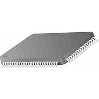
MC9S12E64CFU Freescale Semiconductor, MC9S12E64CFU Datasheet - Page 272

MC9S12E64CFU
Manufacturer Part Number
MC9S12E64CFU
Description
IC MCU 64K FLASH 25MHZ 80-QFP
Manufacturer
Freescale Semiconductor
Series
HCS12r
Specifications of MC9S12E64CFU
Core Processor
HCS12
Core Size
16-Bit
Speed
25MHz
Connectivity
EBI/EMI, I²C, SCI, SPI
Peripherals
POR, PWM, WDT
Number Of I /o
60
Program Memory Size
64KB (64K x 8)
Program Memory Type
FLASH
Ram Size
4K x 8
Voltage - Supply (vcc/vdd)
2.35 V ~ 2.75 V
Data Converters
A/D 16x10b; D/A 2x8b
Oscillator Type
Internal
Operating Temperature
-40°C ~ 85°C
Package / Case
80-QFP
Data Bus Width
16 bit
Data Ram Size
4 KB
Interface Type
SCI, SPI
Maximum Clock Frequency
25 MHz
Number Of Programmable I/os
60
Number Of Timers
16 bit
Maximum Operating Temperature
+ 85 C
Mounting Style
SMD/SMT
Minimum Operating Temperature
- 40 C
On-chip Adc
10 bit
On-chip Dac
8 bit, 2 Channel
For Use With
M68EVB912E128 - BOARD EVAL FOR MC9S12E128/64
Lead Free Status / RoHS Status
Contains lead / RoHS non-compliant
Eeprom Size
-
Lead Free Status / Rohs Status
No RoHS Version Available
Available stocks
Company
Part Number
Manufacturer
Quantity
Price
Company:
Part Number:
MC9S12E64CFU
Manufacturer:
Freescale Semiconductor
Quantity:
10 000
Company:
Part Number:
MC9S12E64CFUE
Manufacturer:
Freescale Semiconductor
Quantity:
10 000
Part Number:
MC9S12E64CFUE
Manufacturer:
FREESCALE
Quantity:
20 000
Company:
Part Number:
MC9S12E64CFUER
Manufacturer:
Freescale Semiconductor
Quantity:
10 000
- Current page: 272 of 606
- Download datasheet (4Mb)
Chapter 8 Serial Communication Interface (SCIV3)
8.4.5.5.2
Figure 8-23
instead of RT16 but continues to be sampled at RT8, RT9, and RT10.
For an 8-bit data character, it takes the receiver 9 bit times x 16 RTr cycles + 10 RTr cycles = 154 RTr
cycles to finish data sampling of the stop bit.
With the misaligned character shown in
the count of the transmitting device is 10 bit times x 16 RTt cycles = 160 RTt cycles.
The maximum percent difference between the receiver count and the transmitter count of a fast 8-bit
character with no errors is:
For a 9-bit data character, it takes the receiver 10 bit times x 16 RTr cycles + 10 RTr cycles = 170 RTr
cycles to finish data sampling of the stop bit.
With the misaligned character shown in
the count of the transmitting device is 11 bit times x 16 RTt cycles = 176 RTt cycles.
The maximum percent difference between the receiver count and the transmitter count of a fast 9-bit
character with no errors is:
8.4.5.6
To enable the SCI to ignore transmissions intended only for other receivers in multiple-receiver systems,
the receiver can be put into a standby state. Setting the receiver wakeup bit, RWU, in SCI control register 2
(SCICR2) puts the receiver into standby state during which receiver interrupts are disabled.The SCI will
continue to load the receive data into the SCIDRH/L registers, but it will not set the RDRF flag.
The transmitting device can address messages to selected receivers by including addressing information
in the initial frame or frames of each message.
The WAKE bit in SCI control register 1 (SCICR1) determines how the SCI is brought out of the standby
state to process an incoming message. The WAKE bit enables either idle line wakeup or address mark
wakeup.
272
((160 – 154) / 160) x 100 = 3.75%
((176 – 170) / 176) x 100 = 3.40%
shows how much a fast received frame can be misaligned. The fast stop bit ends at RT10
Receiver Wakeup
Fast Data Tolerance
RECEIVER
RT CLOCK
MC9S12E128 Data Sheet, Rev. 1.07
Figure
Figure
Figure 8-23. Fast Data
STOP
8-23, the receiver counts 154 RTr cycles at the point when
8-23, the receiver counts 170 RTr cycles at the point when
SAMPLES
DATA
IDLE OR NEXT FRAME
Freescale Semiconductor
Related parts for MC9S12E64CFU
Image
Part Number
Description
Manufacturer
Datasheet
Request
R
Part Number:
Description:
Manufacturer:
Freescale Semiconductor, Inc
Datasheet:
Part Number:
Description:
Manufacturer:
Freescale Semiconductor, Inc
Datasheet:
Part Number:
Description:
Manufacturer:
Freescale Semiconductor, Inc
Datasheet:
Part Number:
Description:
Manufacturer:
Freescale Semiconductor, Inc
Datasheet:
Part Number:
Description:
Manufacturer:
Freescale Semiconductor, Inc
Datasheet:
Part Number:
Description:
Manufacturer:
Freescale Semiconductor, Inc
Datasheet:
Part Number:
Description:
Manufacturer:
Freescale Semiconductor, Inc
Datasheet:
Part Number:
Description:
Manufacturer:
Freescale Semiconductor, Inc
Datasheet:
Part Number:
Description:
Manufacturer:
Freescale Semiconductor, Inc
Datasheet:
Part Number:
Description:
Manufacturer:
Freescale Semiconductor, Inc
Datasheet:
Part Number:
Description:
Manufacturer:
Freescale Semiconductor, Inc
Datasheet:
Part Number:
Description:
Manufacturer:
Freescale Semiconductor, Inc
Datasheet:
Part Number:
Description:
Manufacturer:
Freescale Semiconductor, Inc
Datasheet:
Part Number:
Description:
Manufacturer:
Freescale Semiconductor, Inc
Datasheet:
Part Number:
Description:
Manufacturer:
Freescale Semiconductor, Inc
Datasheet:


