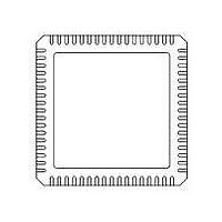
71M6531F-IM/F Maxim Integrated Products, 71M6531F-IM/F Datasheet - Page 102

71M6531F-IM/F
Manufacturer Part Number
71M6531F-IM/F
Description
IC ENERGY METER 256KB 68-QFN
Manufacturer
Maxim Integrated Products
Datasheet
1.71M6531D-IMRF.pdf
(120 pages)
Specifications of 71M6531F-IM/F
Mounting Style
SMD/SMT
Package / Case
QFN-68
Lead Free Status / RoHS Status
Lead free / RoHS Compliant
- Current page: 102 of 120
- Download datasheet (3Mb)
Data Sheet 71M6531D/F-71M6532D/F
5.4.9
5.4.10 LCD DAC
5.4.11 LCD Drivers
The information in
1
†
5.4.12 Optical Interface
102
VLCD is V3P3SYS in MISSION mode and VBAT in BROWNOUT and LCD modes.
Parameter
Maximum Output Power to Crystal
XIN to XOUT Capacitance
Capacitance to GNDD
Parameter
VLCD Voltage
Parameter
VLC2 Voltage
Parameter
OPT_TX V
OPT_TX V
VLC1 Voltage
½ bias, minimum output level
VLC0 Voltage,
VLC1 Impedance
VLC0 Impedance
Specified as percentage of VLC2, the maximum LCD voltage.
V
LCD
XIN
XOUT
=
Crystal Oscillator
V
⅓ bias
½ bias
⅓ bias
3
3 P
OH
OL
⋅
1 (
†
(V3P3D-OPT_TX)
,
−
. 0
Table 80
059
⋅
Table 78: Crystal Oscillator Performance Specifications
Table 81: Optical Interface Performance Specifications
LCD_DAC)
1
© 2005-2010 TERIDIAN Semiconductor Corporation
Table 80: LCD Driver Performance Specifications
Table 79: LCD DAC Performance Specifications
applies to all COM and SEG pins with LCD_DAC[2:0] = 000.
1
−
4
. 0
019
With respect to VLCD
I
I
Crystal connected
RTCA_ADJ[6:0] = 0
With respect to 2*VLC2/3
With respect to VLC2/2
With respect to VLC2/3
∆I
∆I
∆I
∆I
SOURCE
SINK
V
LOAD
LOAD
LOAD
LOAD
1 ≤ LCD_DAC[2:0] ≤ 7
= 20 mA
= 100
= -100
= 100
= -100
Condition
=1 mA
Condition
Condition
Condition
µ
µ
µ
µ
A (Isink)
A (Isink)
A (Isource)
A (Isource)
1
Min
-0.1
-3
-3
-4
Min
Min
Min
-10
Typ
9
9
9
9
Typ
Typ
Typ
FDS 6531/6532 005
+0.1
Max
1.0
+2
+2
+1
15
15
15
15
Max
Max
Max
+10
0.4
0.7
1
3
5
5
% VLC2
% VLC2
Unit
kΩ
kΩ
Unit
Unit
Unit
%
V
V
μW
pF
pF
pF
%
V
V
v1.3
Related parts for 71M6531F-IM/F
Image
Part Number
Description
Manufacturer
Datasheet
Request
R

Part Number:
Description:
IC ENERGY METER 256KB 68-QFN
Manufacturer:
Maxim Integrated Products

Part Number:
Description:
MAX7528KCWPMaxim Integrated Products [CMOS Dual 8-Bit Buffered Multiplying DACs]
Manufacturer:
Maxim Integrated Products
Datasheet:

Part Number:
Description:
Single +5V, fully integrated, 1.25Gbps laser diode driver.
Manufacturer:
Maxim Integrated Products
Datasheet:

Part Number:
Description:
Single +5V, fully integrated, 155Mbps laser diode driver.
Manufacturer:
Maxim Integrated Products
Datasheet:

Part Number:
Description:
VRD11/VRD10, K8 Rev F 2/3/4-Phase PWM Controllers with Integrated Dual MOSFET Drivers
Manufacturer:
Maxim Integrated Products
Datasheet:

Part Number:
Description:
Highly Integrated Level 2 SMBus Battery Chargers
Manufacturer:
Maxim Integrated Products
Datasheet:

Part Number:
Description:
Current Monitor and Accumulator with Integrated Sense Resistor; ; Temperature Range: -40°C to +85°C
Manufacturer:
Maxim Integrated Products

Part Number:
Description:
TSSOP 14/A°/RS-485 Transceivers with Integrated 100O/120O Termination Resis
Manufacturer:
Maxim Integrated Products

Part Number:
Description:
TSSOP 14/A°/RS-485 Transceivers with Integrated 100O/120O Termination Resis
Manufacturer:
Maxim Integrated Products

Part Number:
Description:
QFN 16/A°/AC-DC and DC-DC Peak-Current-Mode Converters with Integrated Step
Manufacturer:
Maxim Integrated Products

Part Number:
Description:
TDFN/A/65V, 1A, 600KHZ, SYNCHRONOUS STEP-DOWN REGULATOR WITH INTEGRATED SWI
Manufacturer:
Maxim Integrated Products

Part Number:
Description:
Integrated Temperature Controller f
Manufacturer:
Maxim Integrated Products

Part Number:
Description:
SOT23-6/I°/45MHz to 650MHz, Integrated IF VCOs with Differential Output
Manufacturer:
Maxim Integrated Products

Part Number:
Description:
SOT23-6/I°/45MHz to 650MHz, Integrated IF VCOs with Differential Output
Manufacturer:
Maxim Integrated Products

Part Number:
Description:
EVALUATION KIT/2.4GHZ TO 2.5GHZ 802.11G/B RF TRANSCEIVER WITH INTEGRATED PA
Manufacturer:
Maxim Integrated Products


