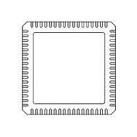
71M6531F-IM/F Maxim Integrated Products, 71M6531F-IM/F Datasheet - Page 43

71M6531F-IM/F
Manufacturer Part Number
71M6531F-IM/F
Description
IC ENERGY METER 256KB 68-QFN
Manufacturer
Maxim Integrated Products
Datasheet
1.71M6531D-IMRF.pdf
(120 pages)
Specifications of 71M6531F-IM/F
Mounting Style
SMD/SMT
Package / Case
QFN-68
Lead Free Status / RoHS Status
Lead free / RoHS Compliant
- Current page: 43 of 120
- Download datasheet (3Mb)
inputs (no current limiting resistors are needed). The Digital I/O pins can be categorized as follows:
pin is configured as DIO, it can be configured independently as an input or output with the DIO_DIR bits
or the LCD_SEGn registers. Input and output data are written to or read from the pins using SFR registers
P0, P1, and P2.
data registers.
FDS 6531/6532 005
1.5.8
The 71M6532D/F includes up to 43 pins of general-purpose digital I/O. These pins are compatible with 5 V
On reset or power-up, all DIO pins are inputs until they are configured for the desired direction under
MPU control. The pin function can be configured by the I/O RAM bits LCD_BITMAPn. Setting
LCD_BITMAPn = 1 configures the pin for LCD, setting LCD_BITMAPn = 0 configures it for DIO. Once a
v1.3
Configuration (DIO
or LCD segment)
Data Register
Direction Register
0 = input,
1 = output
Internal Resources
Configurable
Configuration (DIO
or LCD segment)
Data Register
Direction Register
0 = input,
1 = output
• Dedicated DIO pins (4 pins):
• DIO/LCD segment pins (a total of 37 pins):
• DIO pins combined with other functions (2 pins): DIO2/OPT_TX, DIO1/OPT_RX
LCD Segment
LCD Segment
Pin number
Pin number
Table 43: Data/Direction Registers and Internal Resources for DIO 16-30 (71M6532D/F)
Table 42: Data/Direction Registers and Internal Resources for DIO 1-15 (71M6532D/F)
Digital I/O – 71M6532D/F
o
o
o
o
o
o
DIO
DIO
DIO3
DIO56 – DIO58 (3 pins)
DIO4/SEG24 – DIO27/SEG47 (24 pins)
DIO29/SEG49, DIO30/SEG50 (2 pins)
DIO40/SEG60 – DIO45/SEG65 (6 pins)
DIO47/SEG67 – DIO51/SEG71 (5 pins)
Table 42
PB
92
LCD_BITMAP[39:32]
Y
–
0
–
16
36
33
4
0
–
© 2005-2010 TERIDIAN Semiconductor Corporation
to
Always DIO
Table 44
87
Y
1
–
1
1
17
37
12
5
1
1
DIO0 = P0 (SFR 0x80)
DIO_DIR0 (SFR 0xA2)
DIO2 = P2 (SFR 0xA0)
DIO_DIR2 (SFR 0xA1)
Y
2
–
3
2
2
18
18
13
6
2
–
shows the DIO pins with their configuration, direction control and
17
Y
3
–
3
3
19
39
64
7
3
3
24
60
Y
4
0
4
4
20
40
65
0
4
4
25
61
Y
5
1
5
5
21
41
66
1
5
5
LCD_BITMAP[31:24]
26
62
Y
LCD_BITMAP[47:40]
6
2
6
6
22
42
93
2
6
–
27
63
7
Y
3
7
7
23
43
54
3
7
–
28
67
Y
8
4
0
0
24
44
46
–
0
–
Data Sheet 71M6531D/F-71M6532D/F
29
68
9
5
1
1
Y
25
45
43
–
1
–
DIO1 = P1 (SFR 0x90)
DIO_DIR1 (SFR 0x91)
DIO3 = P3 (SFR 0xB0)
10
30
69
Y
6
2
2
26
46
42
–
2
–
11
31
70 100
Y
7
3
3
27
47
41
–
3
–
LCD_BITMAP[39:32]
12
32
LCD_BITMAP[55:48]
0
4
4
–
–
–
–
–
–
–
13
33
44
29
49
32
1
5
5
–
1
5
14
34
29
30
50
35
2
6
6
–
2
6
15
35
30
–
3
7
7
–
–
–
–
–
43
Related parts for 71M6531F-IM/F
Image
Part Number
Description
Manufacturer
Datasheet
Request
R

Part Number:
Description:
IC ENERGY METER 256KB 68-QFN
Manufacturer:
Maxim Integrated Products

Part Number:
Description:
MAX7528KCWPMaxim Integrated Products [CMOS Dual 8-Bit Buffered Multiplying DACs]
Manufacturer:
Maxim Integrated Products
Datasheet:

Part Number:
Description:
Single +5V, fully integrated, 1.25Gbps laser diode driver.
Manufacturer:
Maxim Integrated Products
Datasheet:

Part Number:
Description:
Single +5V, fully integrated, 155Mbps laser diode driver.
Manufacturer:
Maxim Integrated Products
Datasheet:

Part Number:
Description:
VRD11/VRD10, K8 Rev F 2/3/4-Phase PWM Controllers with Integrated Dual MOSFET Drivers
Manufacturer:
Maxim Integrated Products
Datasheet:

Part Number:
Description:
Highly Integrated Level 2 SMBus Battery Chargers
Manufacturer:
Maxim Integrated Products
Datasheet:

Part Number:
Description:
Current Monitor and Accumulator with Integrated Sense Resistor; ; Temperature Range: -40°C to +85°C
Manufacturer:
Maxim Integrated Products

Part Number:
Description:
TSSOP 14/A°/RS-485 Transceivers with Integrated 100O/120O Termination Resis
Manufacturer:
Maxim Integrated Products

Part Number:
Description:
TSSOP 14/A°/RS-485 Transceivers with Integrated 100O/120O Termination Resis
Manufacturer:
Maxim Integrated Products

Part Number:
Description:
QFN 16/A°/AC-DC and DC-DC Peak-Current-Mode Converters with Integrated Step
Manufacturer:
Maxim Integrated Products

Part Number:
Description:
TDFN/A/65V, 1A, 600KHZ, SYNCHRONOUS STEP-DOWN REGULATOR WITH INTEGRATED SWI
Manufacturer:
Maxim Integrated Products

Part Number:
Description:
Integrated Temperature Controller f
Manufacturer:
Maxim Integrated Products

Part Number:
Description:
SOT23-6/I°/45MHz to 650MHz, Integrated IF VCOs with Differential Output
Manufacturer:
Maxim Integrated Products

Part Number:
Description:
SOT23-6/I°/45MHz to 650MHz, Integrated IF VCOs with Differential Output
Manufacturer:
Maxim Integrated Products

Part Number:
Description:
EVALUATION KIT/2.4GHZ TO 2.5GHZ 802.11G/B RF TRANSCEIVER WITH INTEGRATED PA
Manufacturer:
Maxim Integrated Products


