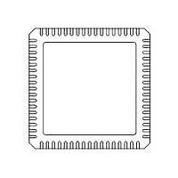
71M6531F-IM/F Maxim Integrated Products, 71M6531F-IM/F Datasheet - Page 25

71M6531F-IM/F
Manufacturer Part Number
71M6531F-IM/F
Description
IC ENERGY METER 256KB 68-QFN
Manufacturer
Maxim Integrated Products
Datasheet
1.71M6531D-IMRF.pdf
(120 pages)
Specifications of 71M6531F-IM/F
Mounting Style
SMD/SMT
Package / Case
QFN-68
Lead Free Status / RoHS Status
Lead free / RoHS Compliant
- Current page: 25 of 120
- Download datasheet (3Mb)
FDS 6531/6532 005
v1.3
ERASE
(FLSH_ERASE)
FL_BANK
PGADDR
(FLSH_PGADR[5:0])
FLSHCRL
IFLAGS
INTBITS
(INT0 … INT6)
(Alternate Name)
Register
0xB6[2:0]
0xF8[6:0]
Address
0xB2[0]
0xB2[1]
0xB2[6]
0xB2[7]
0xE8[0]
0xE8[1]
0xE8[2]
0xE8[3]
0xE8[4]
0xE8[5]
0xE8[6]
0xE8[7]
0xF8[7]
© 2005-2010 TERIDIAN Semiconductor Corporation
0xB7
0x94
SFR
Only byte operations on the entire INTBITS register should be used when
writing. The byte must have all bits set except the bits that are to be
cleared.
IE_XFER
INT6 … INT0
FLSH_PWE
FLSH_MEEN
SECURE
PREBOOT
IE_RTC
FWCOL1
FWCOL0
IE_PB
IE_WAKE
PLL_RISE
PLL_FALL
WD_RST
Bit Field
Name
R/W
R/W Flash Bank Selection.
R/W
R/W
R/W
R/W
R/W
R/W
R/W
R/W
R/W
R/W
R/W
W
W
W
R
R
This register is used to initiate either the Flash
Mass Erase cycle or the Flash Page Erase cycle.
See the
Flash Page Erase Address register. Contains
the flash memory page address (page 0 through
page 127) that will be erased during the Page
Erase cycle (default = 0x00).
Must be re-written for each new Page Erase
cycle.
Program Write Enable:
Mass Erase Enable:
Must be re-written for each new Mass Erase
cycle.
Enables security provisions that prevent external
reading of flash memory and CE program RAM.
This bit is reset on chip reset and may only be
set. Attempts to write zero are ignored.
Indicates that the preboot sequence is active.
This flag monitors the XFER_BUSY interrupt.
It is set by hardware and must be cleared by
the interrupt handler.
This flag monitors the RTC_1SEC interrupt. It
is set by the hardware and must be cleared by
the interrupt handler.
This flag indicates that a flash write was in
progress while the CE was busy.
This flag indicates that a flash write was
attempted when the CE was attempting to
begin a code pass.
This flag indicates that the wake-up pushbutton
was pressed.
This flag indicates that the MPU was awakened
by the autowake timer.
PLL_RISE Interrupt Flag:
Write 0 to clear the PLL_RISE interrupt flag.
PLL_FALL Interrupt Flag:
Write 0 to clear the PLL_FALL interrupt flag.
Interrupt inputs. The MPU may read these bits
to see the status of external interrupts INT0 up
to INT6. These bits do not have any memory
and are primarily intended for debug use.
The WDT is reset when a 1 is written to this
bit.
0: MOVX commands refer to XRAM
1: MOVX @DPTR,A moves A to Program
0: Mass Erase disabled (default).
1: Mass Erase enabled.
Space (Flash) @ DPTR.
Space, normal operation (default).
Flash Memory
Data Sheet 71M6531D/F-71M6532D/F
Description
section for details.
25
Related parts for 71M6531F-IM/F
Image
Part Number
Description
Manufacturer
Datasheet
Request
R

Part Number:
Description:
IC ENERGY METER 256KB 68-QFN
Manufacturer:
Maxim Integrated Products

Part Number:
Description:
MAX7528KCWPMaxim Integrated Products [CMOS Dual 8-Bit Buffered Multiplying DACs]
Manufacturer:
Maxim Integrated Products
Datasheet:

Part Number:
Description:
Single +5V, fully integrated, 1.25Gbps laser diode driver.
Manufacturer:
Maxim Integrated Products
Datasheet:

Part Number:
Description:
Single +5V, fully integrated, 155Mbps laser diode driver.
Manufacturer:
Maxim Integrated Products
Datasheet:

Part Number:
Description:
VRD11/VRD10, K8 Rev F 2/3/4-Phase PWM Controllers with Integrated Dual MOSFET Drivers
Manufacturer:
Maxim Integrated Products
Datasheet:

Part Number:
Description:
Highly Integrated Level 2 SMBus Battery Chargers
Manufacturer:
Maxim Integrated Products
Datasheet:

Part Number:
Description:
Current Monitor and Accumulator with Integrated Sense Resistor; ; Temperature Range: -40°C to +85°C
Manufacturer:
Maxim Integrated Products

Part Number:
Description:
TSSOP 14/A°/RS-485 Transceivers with Integrated 100O/120O Termination Resis
Manufacturer:
Maxim Integrated Products

Part Number:
Description:
TSSOP 14/A°/RS-485 Transceivers with Integrated 100O/120O Termination Resis
Manufacturer:
Maxim Integrated Products

Part Number:
Description:
QFN 16/A°/AC-DC and DC-DC Peak-Current-Mode Converters with Integrated Step
Manufacturer:
Maxim Integrated Products

Part Number:
Description:
TDFN/A/65V, 1A, 600KHZ, SYNCHRONOUS STEP-DOWN REGULATOR WITH INTEGRATED SWI
Manufacturer:
Maxim Integrated Products

Part Number:
Description:
Integrated Temperature Controller f
Manufacturer:
Maxim Integrated Products

Part Number:
Description:
SOT23-6/I°/45MHz to 650MHz, Integrated IF VCOs with Differential Output
Manufacturer:
Maxim Integrated Products

Part Number:
Description:
SOT23-6/I°/45MHz to 650MHz, Integrated IF VCOs with Differential Output
Manufacturer:
Maxim Integrated Products

Part Number:
Description:
EVALUATION KIT/2.4GHZ TO 2.5GHZ 802.11G/B RF TRANSCEIVER WITH INTEGRATED PA
Manufacturer:
Maxim Integrated Products


