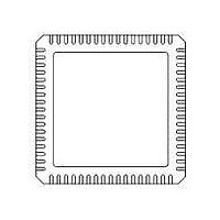
71M6531F-IM/F Maxim Integrated Products, 71M6531F-IM/F Datasheet - Page 78

71M6531F-IM/F
Manufacturer Part Number
71M6531F-IM/F
Description
IC ENERGY METER 256KB 68-QFN
Manufacturer
Maxim Integrated Products
Datasheet
1.71M6531D-IMRF.pdf
(120 pages)
Specifications of 71M6531F-IM/F
Mounting Style
SMD/SMT
Package / Case
QFN-68
Lead Free Status / RoHS Status
Lead free / RoHS Compliant
- Current page: 78 of 120
- Download datasheet (3Mb)
Data Sheet 71M6531D/F-71M6532D/F
78
COMP_STAT[0]
DI_RPB[2:0]
DIO_R1[2:0]
DIO_R2[2:0]
DIO_R4[2:0]
DIO_R5[2:0]
DIO_R6[2:0]
DIO_R7[2:0]
DIO_R8[2:0]
DIO_R9[2:0]
DIO_R10[2:0]
DIO_R11[2:0]
DIO_RRX[2:0]
DIO_DIR0[7:1]
DIO_DIR1[7:0]
DIO_DIR2[1]
DIO_0[7:0]
DIO_1[7:0]
DIO_2[1]
DIO_3[5:4]
DIO_EEX[1:0]
Name
SFR A2 [7:1]
2003[0]
2009[2:0]
2009[6:4]
200A[2:0]
200B[2:0]
200B[6:4]
200C[2:0]
200C[6:4]
200D[2:0]
200D[6:4]
200E[2:0]
200E[6:4]
20AF[2:0]
SFR 91
SFR A1[1]
SFR 80
SFR 90
SFR A0[1]
SFR B0[5:4]
2008[7:6]
Location
Reset
–
0
0
0
0
0
0
0
0
0
0
0
0
0
0
0
0
0
0
0
0
Wake
–
0
0
0
0
0
0
0
0
0
0
0
0
–
–
–
−
–
–
–
0
© 2005-2010 TERIDIAN Semiconductor Corporation
R/W
R/W
R/W
R/W
R/W
R/W
R/W
R/W
R/W
Dir
R
Status bit for the V1 comparator (same as V1_OK, see TMUXOUT)
Connects dedicated I/O pins DIO2 and DIO4 through DIO11 as well as input pins PB,
DIO1 and RX to internal resources. If more than one input is connected to the same
resource, the Multiple column in the table below specifies how they are combined.
Programs the direction of DIO pins 7 through 1. 1 indicates an output. The bits are
ignored if the pin is not configured as DIO. See DIO_PV and DIO_PW for special options
for DIO6 and DIO7. See DIO_EEX[1:0] for special options for DIO4 and DIO5.
Programs the direction of DIO pins 15 through 8. 1 indicates an output. The bits are
ignored if the pin is not configured as I/O. See DIO_PX and DIO_PW for special options
for the DIO8 and DIO9 outputs.
Programs the direction of DIO17.
The value on the DIO pins. Pins configured as LCD will read zero. When written, changes
data on pins configured as outputs. Pins configured as LCD or input will ignore writes.
When set, converts DIO4 and DIO5 to interface with external EEPROM. DIO4 becomes
SDCK and DIO5 becomes bi-directional SDATA.
DIO_Rx[2:0]
DIO_EEX[1:0]
DIO_0[7:1] corresponds to DIO7 through DIO1. PB is read on DIO_0[0].
DIO_1[7:0] corresponds to DIO15 through DIO8.
DIO_2[1] corresponds to DIO17.
DIO_3[5:4] corresponds to DIO28 and DIO29.
000
001
010
011
100
101
110
111
00
01
10
11
Resource
NONE
Reserved
T0 (Counter /Timer 0 clock or gate)
T1 (Counter /Timer 1 clock or gate)
High priority IO interrupt (int0 rising)
Low priority IO interrupt (int1 rising)
High priority IO interrupt (int0 fall-
ing)
Low priority IO interrupt (int1 falling)
Function
Disable EEPROM interface
2-Wire EEPROM interface
3-Wire EEPROM interface
not used
Description
Multiple
OR
OR
OR
OR
OR
OR
OR
–
FDS 6531/6532 005
v1.3
Related parts for 71M6531F-IM/F
Image
Part Number
Description
Manufacturer
Datasheet
Request
R

Part Number:
Description:
IC ENERGY METER 256KB 68-QFN
Manufacturer:
Maxim Integrated Products

Part Number:
Description:
MAX7528KCWPMaxim Integrated Products [CMOS Dual 8-Bit Buffered Multiplying DACs]
Manufacturer:
Maxim Integrated Products
Datasheet:

Part Number:
Description:
Single +5V, fully integrated, 1.25Gbps laser diode driver.
Manufacturer:
Maxim Integrated Products
Datasheet:

Part Number:
Description:
Single +5V, fully integrated, 155Mbps laser diode driver.
Manufacturer:
Maxim Integrated Products
Datasheet:

Part Number:
Description:
VRD11/VRD10, K8 Rev F 2/3/4-Phase PWM Controllers with Integrated Dual MOSFET Drivers
Manufacturer:
Maxim Integrated Products
Datasheet:

Part Number:
Description:
Highly Integrated Level 2 SMBus Battery Chargers
Manufacturer:
Maxim Integrated Products
Datasheet:

Part Number:
Description:
Current Monitor and Accumulator with Integrated Sense Resistor; ; Temperature Range: -40°C to +85°C
Manufacturer:
Maxim Integrated Products

Part Number:
Description:
TSSOP 14/A°/RS-485 Transceivers with Integrated 100O/120O Termination Resis
Manufacturer:
Maxim Integrated Products

Part Number:
Description:
TSSOP 14/A°/RS-485 Transceivers with Integrated 100O/120O Termination Resis
Manufacturer:
Maxim Integrated Products

Part Number:
Description:
QFN 16/A°/AC-DC and DC-DC Peak-Current-Mode Converters with Integrated Step
Manufacturer:
Maxim Integrated Products

Part Number:
Description:
TDFN/A/65V, 1A, 600KHZ, SYNCHRONOUS STEP-DOWN REGULATOR WITH INTEGRATED SWI
Manufacturer:
Maxim Integrated Products

Part Number:
Description:
Integrated Temperature Controller f
Manufacturer:
Maxim Integrated Products

Part Number:
Description:
SOT23-6/I°/45MHz to 650MHz, Integrated IF VCOs with Differential Output
Manufacturer:
Maxim Integrated Products

Part Number:
Description:
SOT23-6/I°/45MHz to 650MHz, Integrated IF VCOs with Differential Output
Manufacturer:
Maxim Integrated Products

Part Number:
Description:
EVALUATION KIT/2.4GHZ TO 2.5GHZ 802.11G/B RF TRANSCEIVER WITH INTEGRATED PA
Manufacturer:
Maxim Integrated Products


