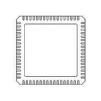
71M6531F-IM/F Maxim Integrated Products, 71M6531F-IM/F Datasheet - Page 65

71M6531F-IM/F
Manufacturer Part Number
71M6531F-IM/F
Description
IC ENERGY METER 256KB 68-QFN
Manufacturer
Maxim Integrated Products
Datasheet
1.71M6531D-IMRF.pdf
(120 pages)
Specifications of 71M6531F-IM/F
Mounting Style
SMD/SMT
Package / Case
QFN-68
Lead Free Status / RoHS Status
Lead free / RoHS Compliant
- Current page: 65 of 120
- Download datasheet (3Mb)
of VREF, using the CE register GAIN_ADJ. Since the band gap amplifier is chopper-stabilized, the most
significant long-term drift mechanism in the voltage reference is removed.
The following formula is used to determine the GAIN_ADJ value of the CE. In this formula, TEMP_X is the
deviation from nominal or calibration temperature expressed in multiples of 0.1 °C:
3. After periods of operation under battery power, the temperature for the time the meter was not powered
FDS 6531/6532 005
3.4.2
The bandgap temperature is used to digitally compensate the power outputs for the temperature dependence
3.4.3
In a production electricity meter, the 71M6531 or 71M6532D/F is not the only component contributing to
temperature dependency. A whole range of components (e.g. current transformers, resistor dividers,
power sources, filter capacitors) will contribute temperature effects.
Since the output of the on-chip temperature sensor is accessible to the MPU, temperature compensation
mechanisms with great flexibility are possible. MPU access to GAIN_ADJ permits a system-wide temperature
correction over the entire meter rather than local to the chip.
3.4.4
In order to obtain accurate readings from the RTC, the following procedure is recommended:
1. At the time of meter calibration, the crystal oscillator is calibrated using the RTCA_ADJ register in I/O
2. When the meter is in service, the MPU takes frequent temperature readings. If the temperature
v1.3
RAM to be as close to 32768 Hz as possible. The recommended procedure is to connect a high-
precision frequency counter to the TMUXOUT pin and select 0x11 for TMUX[4:0]. This will generate
a 4-second pulse at TMUXOUT that can be used to trim RTCA_ADJ to the best value.
characteristics of the crystal are known, the temperature readings can be used to modify the settings
for the I/O RAM registers PREG[16:0] and QREG[1:0] in order to keep the crystal frequency close to
32768 Hz.
can be estimated by averaging the temperatures before and after battery operation. Based on this, the
overall correction for the RTC time can be calculated and applied to the RTC after main power returns
to the meter.
Temperature Compensation for VREF
System Temperature Compensation
Temperature Compensation for the RTC
-1200
-1600
-2000
-2400
-2800
2800
2400
2000
1600
1200
-400
-800
800
400
0
-40
GAIN
_
© 2005-2010 TERIDIAN Semiconductor Corporation
Figure 31: Error Band for VREF over Temperature
ADJ
Error Band (PPM) over Temperature (°C)
-20
=
16385
0
+
TEMP
±40 PPM/°C
±40 PPM/°C
_
2
20
X
14
⋅
PPMC
40
+
TEMP
Data Sheet 71M6531D/F-71M6532D/F
_
60
X
2
23
2
⋅
PPMC
80
2
65
Related parts for 71M6531F-IM/F
Image
Part Number
Description
Manufacturer
Datasheet
Request
R

Part Number:
Description:
IC ENERGY METER 256KB 68-QFN
Manufacturer:
Maxim Integrated Products

Part Number:
Description:
MAX7528KCWPMaxim Integrated Products [CMOS Dual 8-Bit Buffered Multiplying DACs]
Manufacturer:
Maxim Integrated Products
Datasheet:

Part Number:
Description:
Single +5V, fully integrated, 1.25Gbps laser diode driver.
Manufacturer:
Maxim Integrated Products
Datasheet:

Part Number:
Description:
Single +5V, fully integrated, 155Mbps laser diode driver.
Manufacturer:
Maxim Integrated Products
Datasheet:

Part Number:
Description:
VRD11/VRD10, K8 Rev F 2/3/4-Phase PWM Controllers with Integrated Dual MOSFET Drivers
Manufacturer:
Maxim Integrated Products
Datasheet:

Part Number:
Description:
Highly Integrated Level 2 SMBus Battery Chargers
Manufacturer:
Maxim Integrated Products
Datasheet:

Part Number:
Description:
Current Monitor and Accumulator with Integrated Sense Resistor; ; Temperature Range: -40°C to +85°C
Manufacturer:
Maxim Integrated Products

Part Number:
Description:
TSSOP 14/A°/RS-485 Transceivers with Integrated 100O/120O Termination Resis
Manufacturer:
Maxim Integrated Products

Part Number:
Description:
TSSOP 14/A°/RS-485 Transceivers with Integrated 100O/120O Termination Resis
Manufacturer:
Maxim Integrated Products

Part Number:
Description:
QFN 16/A°/AC-DC and DC-DC Peak-Current-Mode Converters with Integrated Step
Manufacturer:
Maxim Integrated Products

Part Number:
Description:
TDFN/A/65V, 1A, 600KHZ, SYNCHRONOUS STEP-DOWN REGULATOR WITH INTEGRATED SWI
Manufacturer:
Maxim Integrated Products

Part Number:
Description:
Integrated Temperature Controller f
Manufacturer:
Maxim Integrated Products

Part Number:
Description:
SOT23-6/I°/45MHz to 650MHz, Integrated IF VCOs with Differential Output
Manufacturer:
Maxim Integrated Products

Part Number:
Description:
SOT23-6/I°/45MHz to 650MHz, Integrated IF VCOs with Differential Output
Manufacturer:
Maxim Integrated Products

Part Number:
Description:
EVALUATION KIT/2.4GHZ TO 2.5GHZ 802.11G/B RF TRANSCEIVER WITH INTEGRATED PA
Manufacturer:
Maxim Integrated Products


