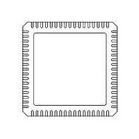
71M6531F-IM/F Maxim Integrated Products, 71M6531F-IM/F Datasheet - Page 18

71M6531F-IM/F
Manufacturer Part Number
71M6531F-IM/F
Description
IC ENERGY METER 256KB 68-QFN
Manufacturer
Maxim Integrated Products
Datasheet
1.71M6531D-IMRF.pdf
(120 pages)
Specifications of 71M6531F-IM/F
Mounting Style
SMD/SMT
Package / Case
QFN-68
Lead Free Status / RoHS Status
Lead free / RoHS Compliant
- Current page: 18 of 120
- Download datasheet (3Mb)
signals to the MPU that accumulated data are available.
The end of each multiplexer cycle is signaled to the MPU by the CE_BUSY interrupt. At the end of each
multiplexer cycle status information, such as sag data and the digitized input signal, is available to the MPU.
Figure 7
50, consisting of 2100 samples of 397 µs each, followed by the XFER_BUSY interrupt. The sampling in
this example is applied to a 50 Hz signal.
There is no correlation between the line signal frequency and the choice of PRE_SAMPS[1:0] or
SUM_CYCLES[5:0] (even though when SUM_CYCLES[5:0] = 42 one set of SUM_CYCLES[5:0] happens to
sample a period of 16.6 ms). Furthermore, sampling does not have to start when the line voltage crosses
the zero line and the length of the accumulation interval need not be an integer multiple of the signal cycles.
Data Sheet 71M6531D/F-71M6532D/F
For example, PRE_SAMPS[1:0] = 42 and SUM_CYCLES[5:0] = 50 will establish 2100 samples per accumulation
cycle. PRE_SAMPS[1:0] = 100 and SUM_CYCLES[5:0] = 21 will result in the exact same accumulation
cycle of 2100 samples or 833 ms. After an accumulation cycle is completed, the XFER_BUSY interrupt
18
shows the accumulation interval resulting from PRE_SAMPS[1:0] = 42 and SUM_CYCLES[5:0] =
20ms
© 2005-2010 TERIDIAN Semiconductor Corporation
Figure 6: Samples from Multiplexer Cycle
Figure 7: Accumulation Interval
IA
VA
833ms
IB
VB
13/32768Hz = 397µs
per mux cycle
1/32768Hz =
30.518µs
Interrupt to MPU
FDS 6531/6532 005
XFER_BUSY
v1.3
Related parts for 71M6531F-IM/F
Image
Part Number
Description
Manufacturer
Datasheet
Request
R

Part Number:
Description:
IC ENERGY METER 256KB 68-QFN
Manufacturer:
Maxim Integrated Products

Part Number:
Description:
MAX7528KCWPMaxim Integrated Products [CMOS Dual 8-Bit Buffered Multiplying DACs]
Manufacturer:
Maxim Integrated Products
Datasheet:

Part Number:
Description:
Single +5V, fully integrated, 1.25Gbps laser diode driver.
Manufacturer:
Maxim Integrated Products
Datasheet:

Part Number:
Description:
Single +5V, fully integrated, 155Mbps laser diode driver.
Manufacturer:
Maxim Integrated Products
Datasheet:

Part Number:
Description:
VRD11/VRD10, K8 Rev F 2/3/4-Phase PWM Controllers with Integrated Dual MOSFET Drivers
Manufacturer:
Maxim Integrated Products
Datasheet:

Part Number:
Description:
Highly Integrated Level 2 SMBus Battery Chargers
Manufacturer:
Maxim Integrated Products
Datasheet:

Part Number:
Description:
Current Monitor and Accumulator with Integrated Sense Resistor; ; Temperature Range: -40°C to +85°C
Manufacturer:
Maxim Integrated Products

Part Number:
Description:
TSSOP 14/A°/RS-485 Transceivers with Integrated 100O/120O Termination Resis
Manufacturer:
Maxim Integrated Products

Part Number:
Description:
TSSOP 14/A°/RS-485 Transceivers with Integrated 100O/120O Termination Resis
Manufacturer:
Maxim Integrated Products

Part Number:
Description:
QFN 16/A°/AC-DC and DC-DC Peak-Current-Mode Converters with Integrated Step
Manufacturer:
Maxim Integrated Products

Part Number:
Description:
TDFN/A/65V, 1A, 600KHZ, SYNCHRONOUS STEP-DOWN REGULATOR WITH INTEGRATED SWI
Manufacturer:
Maxim Integrated Products

Part Number:
Description:
Integrated Temperature Controller f
Manufacturer:
Maxim Integrated Products

Part Number:
Description:
SOT23-6/I°/45MHz to 650MHz, Integrated IF VCOs with Differential Output
Manufacturer:
Maxim Integrated Products

Part Number:
Description:
SOT23-6/I°/45MHz to 650MHz, Integrated IF VCOs with Differential Output
Manufacturer:
Maxim Integrated Products

Part Number:
Description:
EVALUATION KIT/2.4GHZ TO 2.5GHZ 802.11G/B RF TRANSCEIVER WITH INTEGRATED PA
Manufacturer:
Maxim Integrated Products


