C8051F226DK Silicon Laboratories Inc, C8051F226DK Datasheet - Page 100
C8051F226DK
Manufacturer Part Number
C8051F226DK
Description
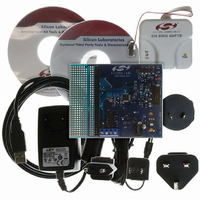
DEV KIT F220/221/226/230/231/236
Manufacturer
Silicon Laboratories Inc
Type
MCUr
Datasheet
1.C8051F226DK.pdf
(146 pages)
Specifications of C8051F226DK
Contents
Evaluation Board, Power Supply, USB Cables, Adapter and Documentation
Processor To Be Evaluated
C8051F22x and C8051F23x
Interface Type
USB
Silicon Manufacturer
Silicon Labs
Core Architecture
8051
Silicon Core Number
C8051F226
Silicon Family Name
C8051F2xx
Lead Free Status / RoHS Status
Contains lead / RoHS non-compliant
For Use With/related Products
C8051F220, 221, 226, 230, 231, 236
Lead Free Status / Rohs Status
Lead free / RoHS Compliant
Other names
336-1241


C8051F2xx
13.1. External Crystal Example
If a crystal were used to generate the system clock for the MCU, the circuit would be as shown in
Figure 13.1, Option 1. For an ECS-110.5-20-4 crystal, the resonate frequency is 11.0592 MHz, the intrin-
sic capacitance is 7 pF, and the ESR is 60 W. The compensation capacitors should be 33 pF each, and
the PWB parasitic capacitance is estimated to be 2 pF. The appropriate External Oscillator Frequency
Control value (XFCN) from the Crystal column in the table in SFR Definition 13.2 (OSCXCN Register)
should be 111b.
The Crystal Oscillator Valid Flag (XTLVLD in register OSCXCN) is set to logic 1 by hardware when the
external oscillator is running and stable. The XTLVLD detection circuit requires a startup time of at least
1ms between enabling the oscillator and checking the XTLVLD flag. Switching to the external oscillator
before 1ms can result in unpredictable behavior. The recommend procedure is:
Switching to the external oscillator before the crystal oscillator has stabilized could result in unpredictable
behavior.
NOTE: Crystal oscillator circuits are quite sensitive to PCB layout. The crystal should be placed as close
as possible to the XTAL pins on the device, keeping the traces as short as possible and shielded with
ground plane from any other traces which could introduce noise or interference.
13.2. External RC Example
If an external RC network were used to generate the system clock for the MCU, the circuit would be as
shown in Figure 13.1, Option 2. The capacitor must be no greater than 100 pF, but using a very small
capacitor will increase the frequency drift due to the PWB parasitic capacitance. To determine the required
External Oscillator Frequency Control value (XFCN) in the OSCXCN Register, first select the RC network
value to produce the desired frequency of oscillation. If the frequency desired is 100 kHz, let R = 246 kW
and C = 50 pF:
13.3. External Capacitor Example
If an external capacitor were used to generate the system clock for the MCU, the circuit would be as shown
in Figure 13.1, Option 3. The capacitor must be no greater than 100 pF, but using a very small capacitor
will increase the frequency drift due to the PWB parasitic capacitance. To determine the required External
Oscillator Frequency Control value (XFCN) in the OSCXCN Register, select the capacitor to be used and
find the frequency of oscillation from the equations below. Assume V
If a frequency of roughly 90kHz is desired, select the K Factor from the table in SFR Definition 13.2 as KF
= 13:
Therefore, the XFCN value to use in this example is 011.
100
1. Enable the external oscillator
2. Wait 1 ms
3. Poll for XTLVLD '0' ==> '1'
4. Switch to the external oscillator
f = 1.23(103)/RC = 1.23(103) / [246 x 50] = 0.1 MHz = 100 kHz
XFCN ³ log2(f/25 kHz)
XFCN ³ log2(100 kHz/25 kHz) = log2(4)
XFCN ³ 2, or code 010
f = KF / (C x V
f = KF / 150
f = 13 /150 = 0.087 MHz, or 87 kHz
DD
) = KF / (50 x 3)
Rev. 1.6
DD
= 3.0 V and C = 50 pF:
Related parts for C8051F226DK
Image
Part Number
Description
Manufacturer
Datasheet
Request
R

Part Number:
Description:
SMD/C°/SINGLE-ENDED OUTPUT SILICON OSCILLATOR
Manufacturer:
Silicon Laboratories Inc
Part Number:
Description:
Manufacturer:
Silicon Laboratories Inc
Datasheet:
Part Number:
Description:
N/A N/A/SI4010 AES KEYFOB DEMO WITH LCD RX
Manufacturer:
Silicon Laboratories Inc
Datasheet:
Part Number:
Description:
N/A N/A/SI4010 SIMPLIFIED KEY FOB DEMO WITH LED RX
Manufacturer:
Silicon Laboratories Inc
Datasheet:
Part Number:
Description:
N/A/-40 TO 85 OC/EZLINK MODULE; F930/4432 HIGH BAND (REV E/B1)
Manufacturer:
Silicon Laboratories Inc
Part Number:
Description:
EZLink Module; F930/4432 Low Band (rev e/B1)
Manufacturer:
Silicon Laboratories Inc
Part Number:
Description:
I°/4460 10 DBM RADIO TEST CARD 434 MHZ
Manufacturer:
Silicon Laboratories Inc
Part Number:
Description:
I°/4461 14 DBM RADIO TEST CARD 868 MHZ
Manufacturer:
Silicon Laboratories Inc
Part Number:
Description:
I°/4463 20 DBM RFSWITCH RADIO TEST CARD 460 MHZ
Manufacturer:
Silicon Laboratories Inc
Part Number:
Description:
I°/4463 20 DBM RADIO TEST CARD 868 MHZ
Manufacturer:
Silicon Laboratories Inc
Part Number:
Description:
I°/4463 27 DBM RADIO TEST CARD 868 MHZ
Manufacturer:
Silicon Laboratories Inc
Part Number:
Description:
I°/4463 SKYWORKS 30 DBM RADIO TEST CARD 915 MHZ
Manufacturer:
Silicon Laboratories Inc
Part Number:
Description:
N/A N/A/-40 TO 85 OC/4463 RFMD 30 DBM RADIO TEST CARD 915 MHZ
Manufacturer:
Silicon Laboratories Inc
Part Number:
Description:
I°/4463 20 DBM RADIO TEST CARD 169 MHZ
Manufacturer:
Silicon Laboratories Inc