C8051F226DK Silicon Laboratories Inc, C8051F226DK Datasheet - Page 4
C8051F226DK
Manufacturer Part Number
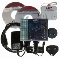
C8051F226DK
Description
DEV KIT F220/221/226/230/231/236
Manufacturer
Silicon Laboratories Inc
Type
MCUr
Datasheet
1.C8051F226DK.pdf
(146 pages)
Specifications of C8051F226DK
Contents
Evaluation Board, Power Supply, USB Cables, Adapter and Documentation
Processor To Be Evaluated
C8051F22x and C8051F23x
Interface Type
USB
Silicon Manufacturer
Silicon Labs
Core Architecture
8051
Silicon Core Number
C8051F226
Silicon Family Name
C8051F2xx
Lead Free Status / RoHS Status
Contains lead / RoHS non-compliant
For Use With/related Products
C8051F220, 221, 226, 230, 231, 236
Lead Free Status / Rohs Status
Lead free / RoHS Compliant
Other names
336-1241


C8051F2xx
10. Flash Memory ......................................................................................................... 85
11. On-Chip XRAM (C8051F206/226/236).................................................................... 90
12. Reset Sources......................................................................................................... 91
13. Oscillator ................................................................................................................. 97
14. Port Input/Output.................................................................................................. 101
15. Serial Peripheral Interface Bus ........................................................................... 110
16. UART...................................................................................................................... 117
17. Timers.................................................................................................................... 125
4
9.5. Power Management Modes .............................................................................. 83
10.1.Programming The Flash Memory ..................................................................... 85
10.2.Security Options ............................................................................................... 86
12.1.Power-on Reset................................................................................................ 92
12.2.Software Forced Reset..................................................................................... 92
12.3.Power-fail Reset ............................................................................................... 92
12.4.External Reset .................................................................................................. 93
12.5.Missing Clock Detector Reset .......................................................................... 93
12.6.Comparator 0 Reset ......................................................................................... 93
12.7.Watchdog Timer Reset..................................................................................... 93
13.1.External Crystal Example ............................................................................... 100
13.2.External RC Example ..................................................................................... 100
13.3.External Capacitor Example ........................................................................... 100
14.1.Port I/O Initialization ....................................................................................... 101
14.2.General Purpose Port I/O ............................................................................... 105
15.1.Signal Descriptions......................................................................................... 111
15.2.Serial Clock Timing......................................................................................... 113
15.3.SPI Special Function Registers ...................................................................... 113
16.1.UART Operational Modes .............................................................................. 118
16.2.Multiprocessor Communications .................................................................... 122
17.1.Timer 0 and Timer 1 ....................................................................................... 125
9.5.1. Idle Mode.................................................................................................. 83
9.5.2. Stop Mode ................................................................................................ 83
12.7.1.Watchdog Usage...................................................................................... 93
15.1.1.Master Out, Slave In .............................................................................. 111
15.1.2.Master In, Slave Out .............................................................................. 111
15.1.3.Serial Clock ............................................................................................ 111
15.1.4.Slave Select ........................................................................................... 111
16.1.1.Mode 0: Synchronous Mode .................................................................. 118
16.1.2.Mode 1: 8-Bit UART, Variable Baud Rate.............................................. 119
16.1.3.Mode 2: 9-Bit UART, Fixed Baud Rate .................................................. 121
16.1.4.Mode 3: 9-Bit UART, Variable Baud Rate.............................................. 121
17.1.1.Mode 0: 13-bit Counter/Timer ................................................................ 125
17.1.2.Mode 1: 16-bit Counter/Timer ................................................................ 126
17.1.3.Mode 2: 8-bit Counter/Timer with Auto-Reload...................................... 127
17.1.4.Mode 3: Two 8-bit Counter/Timers (Timer 0 Only)................................. 128
Rev. 1.6
Related parts for C8051F226DK
Image
Part Number
Description
Manufacturer
Datasheet
Request
R

Part Number:
Description:
SMD/C°/SINGLE-ENDED OUTPUT SILICON OSCILLATOR
Manufacturer:
Silicon Laboratories Inc
Part Number:
Description:
Manufacturer:
Silicon Laboratories Inc
Datasheet:
Part Number:
Description:
N/A N/A/SI4010 AES KEYFOB DEMO WITH LCD RX
Manufacturer:
Silicon Laboratories Inc
Datasheet:
Part Number:
Description:
N/A N/A/SI4010 SIMPLIFIED KEY FOB DEMO WITH LED RX
Manufacturer:
Silicon Laboratories Inc
Datasheet:
Part Number:
Description:
N/A/-40 TO 85 OC/EZLINK MODULE; F930/4432 HIGH BAND (REV E/B1)
Manufacturer:
Silicon Laboratories Inc
Part Number:
Description:
EZLink Module; F930/4432 Low Band (rev e/B1)
Manufacturer:
Silicon Laboratories Inc
Part Number:
Description:
I°/4460 10 DBM RADIO TEST CARD 434 MHZ
Manufacturer:
Silicon Laboratories Inc
Part Number:
Description:
I°/4461 14 DBM RADIO TEST CARD 868 MHZ
Manufacturer:
Silicon Laboratories Inc
Part Number:
Description:
I°/4463 20 DBM RFSWITCH RADIO TEST CARD 460 MHZ
Manufacturer:
Silicon Laboratories Inc
Part Number:
Description:
I°/4463 20 DBM RADIO TEST CARD 868 MHZ
Manufacturer:
Silicon Laboratories Inc
Part Number:
Description:
I°/4463 27 DBM RADIO TEST CARD 868 MHZ
Manufacturer:
Silicon Laboratories Inc
Part Number:
Description:
I°/4463 SKYWORKS 30 DBM RADIO TEST CARD 915 MHZ
Manufacturer:
Silicon Laboratories Inc
Part Number:
Description:
N/A N/A/-40 TO 85 OC/4463 RFMD 30 DBM RADIO TEST CARD 915 MHZ
Manufacturer:
Silicon Laboratories Inc
Part Number:
Description:
I°/4463 20 DBM RADIO TEST CARD 169 MHZ
Manufacturer:
Silicon Laboratories Inc