C8051F226DK Silicon Laboratories Inc, C8051F226DK Datasheet - Page 83
C8051F226DK
Manufacturer Part Number
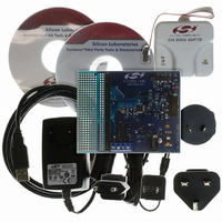
C8051F226DK
Description
DEV KIT F220/221/226/230/231/236
Manufacturer
Silicon Laboratories Inc
Type
MCUr
Datasheet
1.C8051F226DK.pdf
(146 pages)
Specifications of C8051F226DK
Contents
Evaluation Board, Power Supply, USB Cables, Adapter and Documentation
Processor To Be Evaluated
C8051F22x and C8051F23x
Interface Type
USB
Silicon Manufacturer
Silicon Labs
Core Architecture
8051
Silicon Core Number
C8051F226
Silicon Family Name
C8051F2xx
Lead Free Status / RoHS Status
Contains lead / RoHS non-compliant
For Use With/related Products
C8051F220, 221, 226, 230, 231, 236
Lead Free Status / Rohs Status
Lead free / RoHS Compliant
Other names
336-1241


9.5.
The CIP-51 core has two software programmable power management modes: Idle and Stop. Idle mode
halts the CPU while leaving the external peripherals and internal clocks active. In Stop mode, the CPU is
halted, all interrupts and timers (except the Missing Clock Detector) are inactive, and the system clock is
stopped. Since clocks are running in Idle mode, power consumption is dependent upon the system clock
frequency and the number of peripherals left in active mode before entering Idle. Stop mode consumes
the least power. SFR Definition 9.14 describes the Power Control Register (PCON) used to control the
CIP-51’s power management modes.
Although the CIP-51 has Idle and Stop modes built in (as with any standard 8051 architecture), power
management of the entire MCU is better accomplished by enabling/disabling individual peripherals as
needed. Each analog peripheral can be disabled when not in use and put into low power mode. Turning
off the active oscillator saves even more power, but requires a reset to restart the MCU.
9.5.1. Idle Mode
Setting the Idle Mode Select bit (PCON.0) causes the CIP-51 to halt the CPU and enter Idle mode as soon
as the instruction that sets the bit completes.
data. All analog and digital peripherals can remain active during Idle mode.
Idle mode is terminated when an enabled interrupt or RST is asserted. The assertion of an enabled inter-
rupt will cause the Idle Mode Selection bit (PCON.0) to be cleared and the CPU will resume operation.
The pending interrupt will be serviced and the next instruction to be executed after the return from interrupt
(RETI) will be the instruction immediately following the one that set the Idle Mode Select bit. If Idle mode is
terminated by an internal or external reset, the CIP-51 performs a normal reset sequence and begins pro-
gram execution at address 0x0000.
Note: If the instruction following the write of the IDLE bit is a single-byte instruction and an interrupt occurs
during the execution phase of the instruction that sets the IDLE bit, the CPU may not wake from Idle mode
when a future interrupt occurs. Any instructions that set the IDLE bit should be followed by an instruction
that has 2 or more op-code bytes, for example:
// in ‘C’:
PCON |= 0x01;
PCON = PCON;
; in assembly:
ORL PCON, #01h
MOV PCON, PCON
If enabled, the WDT will eventually cause an internal watchdog reset and thereby terminate the Idle mode.
This feature protects the system from an unintended permanent shutdown in the event of an inadvertent
write to the PCON register. If this behavior is not desired, the WDT may be disabled by software prior to
entering the Idle mode if the WDT was initially configured to allow this operation. This provides the oppor-
tunity for additional power savings, allowing the system to remain in the Idle mode indefinitely, waiting for
an external stimulus to wake up the system. Refer to Section 12.7 Watchdog Timer for more information
on the use and configuration of the WDT.
9.5.2. Stop Mode
Setting the Stop Mode Select bit (PCON.1) causes the CIP-51 to enter Stop mode as soon as the instruc-
tion that sets the bit completes. In Stop mode, the CPU and oscillators are stopped, effectively shutting
Power Management Modes
// set IDLE bit
// ... followed by a 3-cycle dummy instruction
; set IDLE bit
; ... followed by a 3-cycle dummy instruction
All internal registers and memory maintain their original
Rev. 1.6
C8051F2xx
83
Related parts for C8051F226DK
Image
Part Number
Description
Manufacturer
Datasheet
Request
R

Part Number:
Description:
SMD/C°/SINGLE-ENDED OUTPUT SILICON OSCILLATOR
Manufacturer:
Silicon Laboratories Inc
Part Number:
Description:
Manufacturer:
Silicon Laboratories Inc
Datasheet:
Part Number:
Description:
N/A N/A/SI4010 AES KEYFOB DEMO WITH LCD RX
Manufacturer:
Silicon Laboratories Inc
Datasheet:
Part Number:
Description:
N/A N/A/SI4010 SIMPLIFIED KEY FOB DEMO WITH LED RX
Manufacturer:
Silicon Laboratories Inc
Datasheet:
Part Number:
Description:
N/A/-40 TO 85 OC/EZLINK MODULE; F930/4432 HIGH BAND (REV E/B1)
Manufacturer:
Silicon Laboratories Inc
Part Number:
Description:
EZLink Module; F930/4432 Low Band (rev e/B1)
Manufacturer:
Silicon Laboratories Inc
Part Number:
Description:
I°/4460 10 DBM RADIO TEST CARD 434 MHZ
Manufacturer:
Silicon Laboratories Inc
Part Number:
Description:
I°/4461 14 DBM RADIO TEST CARD 868 MHZ
Manufacturer:
Silicon Laboratories Inc
Part Number:
Description:
I°/4463 20 DBM RFSWITCH RADIO TEST CARD 460 MHZ
Manufacturer:
Silicon Laboratories Inc
Part Number:
Description:
I°/4463 20 DBM RADIO TEST CARD 868 MHZ
Manufacturer:
Silicon Laboratories Inc
Part Number:
Description:
I°/4463 27 DBM RADIO TEST CARD 868 MHZ
Manufacturer:
Silicon Laboratories Inc
Part Number:
Description:
I°/4463 SKYWORKS 30 DBM RADIO TEST CARD 915 MHZ
Manufacturer:
Silicon Laboratories Inc
Part Number:
Description:
N/A N/A/-40 TO 85 OC/4463 RFMD 30 DBM RADIO TEST CARD 915 MHZ
Manufacturer:
Silicon Laboratories Inc
Part Number:
Description:
I°/4463 20 DBM RADIO TEST CARD 169 MHZ
Manufacturer:
Silicon Laboratories Inc