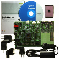
EVB9S08DZ60 Freescale Semiconductor, EVB9S08DZ60 Datasheet - Page 399

EVB9S08DZ60
Manufacturer Part Number
EVB9S08DZ60
Description
BOARD EVAL FOR 9S08DZ60
Manufacturer
Freescale Semiconductor
Type
MCUr
Datasheets
1.DEMO9S08DZ60.pdf
(416 pages)
2.EVB9S08DZ60.pdf
(2 pages)
3.EVB9S08DZ60.pdf
(32 pages)
4.EVB9S08DZ60.pdf
(13 pages)
5.EVB9S08DZ60.pdf
(4 pages)
Specifications of EVB9S08DZ60
Contents
Module and Misc Hardware
Processor To Be Evaluated
S08D
Data Bus Width
8 bit
Interface Type
RS-232, USB
Silicon Manufacturer
Freescale
Core Architecture
HCS08
Core Sub-architecture
HCS08
Silicon Core Number
MC9S08
Silicon Family Name
S08D
Kit Contents
Board Cables CD Power Supply
Rohs Compliant
Yes
For Use With/related Products
MC9S08DZ60
Lead Free Status / RoHS Status
Lead free / RoHS Compliant
Available stocks
Company
Part Number
Manufacturer
Quantity
Price
Company:
Part Number:
EVB9S08DZ60
Manufacturer:
TI
Quantity:
101
- DEMO9S08DZ60 PDF datasheet
- EVB9S08DZ60 PDF datasheet #2
- EVB9S08DZ60 PDF datasheet #3
- EVB9S08DZ60 PDF datasheet #4
- EVB9S08DZ60 PDF datasheet #5
- Current page: 399 of 416
- Download datasheet (5Mb)
Appendix B Timer Pulse-Width Modulator (TPMV2)
In input capture mode, reading either byte (TPMxCnVH or TPMxCnVL) latches the contents of both bytes
into a buffer where they remain latched until the other byte is read. This latching mechanism also resets
(becomes unlatched) when the TPMxCnSC register is written.
In output compare or PWM modes, writing to either byte (TPMxCnVH or TPMxCnVL) latches the value
into a buffer. When both bytes have been written, they are transferred as a coherent 16-bit value into the
timer channel value registers. This latching mechanism may be manually reset by writing to the
TPMxCnSC register.
This latching mechanism allows coherent 16-bit writes in either order, which is friendly to various
compiler implementations.
B.3
Functional Description
All TPM functions are associated with a main 16-bit counter that allows flexible selection of the clock
source and prescale divisor. A 16-bit modulo register also is associated with the main 16-bit counter in the
TPM. Each TPM channel is optionally associated with an MCU pin and a maskable interrupt function.
The TPM has center-aligned PWM capabilities controlled by the CPWMS control bit in TPMxSC. When
CPWMS is set to 1, timer counter TPMxCNT changes to an up-/down-counter and all channels in the
associated TPM act as center-aligned PWM channels. When CPWMS = 0, each channel can
independently be configured to operate in input capture, output compare, or buffered edge-aligned PWM
mode.
The following sections describe the main 16-bit counter and each of the timer operating modes (input
capture, output compare, edge-aligned PWM, and center-aligned PWM). Because details of pin operation
and interrupt activity depend on the operating mode, these topics are covered in the associated mode
sections.
B.3.1
Counter
All timer functions are based on the main 16-bit counter (TPMxCNTH:TPMxCNTL). This section
discusses selection of the clock source, up-counting vs. up-/down-counting, end-of-count overflow, and
manual counter reset.
After any MCU reset, CLKSB:CLKSA = 0:0 so no clock source is selected and the TPM is inactive.
Normally, CLKSB:CLKSA would be set to 0:1 so the bus clock drives the timer counter. The clock source
for the TPM can be selected to be off, the bus clock (BUSCLK), the fixed system clock (XCLK), or an
external input. The maximum frequency allowed for the external clock option is one-fourth the bus rate.
Refer to
Section B.2.1, “Timer Status and Control Register
(TPMxSC)”
and
Table B-2
for more
information about clock source selection.
When the microcontroller is in active background mode, the TPM temporarily suspends all counting until
the microcontroller returns to normal user operating mode. During stop mode, all TPM clocks are stopped;
therefore, the TPM is effectively disabled until clocks resume. During wait mode, the TPM continues to
operate normally.
The main 16-bit counter has two counting modes. When center-aligned PWM is selected (CPWMS = 1),
the counter operates in up-/down-counting mode. Otherwise, the counter operates as a simple up-counter.
MC9S08DZ60 Series Data Sheet, Rev. 4
Freescale Semiconductor
399
Related parts for EVB9S08DZ60
Image
Part Number
Description
Manufacturer
Datasheet
Request
R
Part Number:
Description:
Manufacturer:
Freescale Semiconductor, Inc
Datasheet:
Part Number:
Description:
Manufacturer:
Freescale Semiconductor, Inc
Datasheet:
Part Number:
Description:
Manufacturer:
Freescale Semiconductor, Inc
Datasheet:
Part Number:
Description:
Manufacturer:
Freescale Semiconductor, Inc
Datasheet:
Part Number:
Description:
Manufacturer:
Freescale Semiconductor, Inc
Datasheet:
Part Number:
Description:
Manufacturer:
Freescale Semiconductor, Inc
Datasheet:
Part Number:
Description:
Manufacturer:
Freescale Semiconductor, Inc
Datasheet:
Part Number:
Description:
Manufacturer:
Freescale Semiconductor, Inc
Datasheet:
Part Number:
Description:
Manufacturer:
Freescale Semiconductor, Inc
Datasheet:
Part Number:
Description:
Manufacturer:
Freescale Semiconductor, Inc
Datasheet:
Part Number:
Description:
Manufacturer:
Freescale Semiconductor, Inc
Datasheet:
Part Number:
Description:
Manufacturer:
Freescale Semiconductor, Inc
Datasheet:
Part Number:
Description:
Manufacturer:
Freescale Semiconductor, Inc
Datasheet:
Part Number:
Description:
Manufacturer:
Freescale Semiconductor, Inc
Datasheet:
Part Number:
Description:
Manufacturer:
Freescale Semiconductor, Inc
Datasheet:


