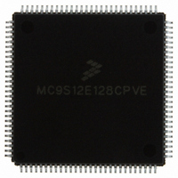
MC9S12E128CPVE Freescale Semiconductor, MC9S12E128CPVE Datasheet - Page 466

MC9S12E128CPVE
Manufacturer Part Number
MC9S12E128CPVE
Description
IC MCU 128K FLASH 25MHZ 112-LQFP
Manufacturer
Freescale Semiconductor
Series
HCS12r
Specifications of MC9S12E128CPVE
Core Processor
HCS12
Core Size
16-Bit
Speed
25MHz
Connectivity
EBI/EMI, I²C, SCI, SPI
Peripherals
POR, PWM, WDT
Number Of I /o
91
Program Memory Size
128KB (128K x 8)
Program Memory Type
FLASH
Ram Size
8K x 8
Voltage - Supply (vcc/vdd)
2.35 V ~ 2.75 V
Data Converters
A/D 16x10b; D/A 2x8b
Oscillator Type
Internal
Operating Temperature
-40°C ~ 85°C
Package / Case
112-LQFP
Processor Series
S12E
Core
HCS12
Data Bus Width
16 bit
Data Ram Size
8 KB
Interface Type
SCI/SPI
Maximum Clock Frequency
25 MHz
Number Of Programmable I/os
92
Number Of Timers
12
Operating Supply Voltage
3.135 V to 5.5 V
Maximum Operating Temperature
+ 85 C
Mounting Style
SMD/SMT
3rd Party Development Tools
EWHCS12
Minimum Operating Temperature
- 40 C
On-chip Adc
16-ch x 10-bit
On-chip Dac
2-ch x 8-bit
Controller Family/series
HCS12/S12X
No. Of I/o's
90
Ram Memory Size
8KB
Cpu Speed
25MHz
No. Of Timers
4
Embedded Interface Type
I2C, SCI, SPI
Rohs Compliant
Yes
For Use With
M68EVB912E128 - BOARD EVAL FOR MC9S12E128/64
Lead Free Status / RoHS Status
Lead free / RoHS Compliant
Eeprom Size
-
Lead Free Status / Rohs Status
Lead free / RoHS Compliant
Available stocks
Company
Part Number
Manufacturer
Quantity
Price
Company:
Part Number:
MC9S12E128CPVE
Manufacturer:
Freescale Semiconductor
Quantity:
10 000
- Current page: 466 of 606
- Download datasheet (4Mb)
Chapter 15 Background Debug Module (BDMV4)
15.4.8
The abort procedure is based on the SYNC command. In order to abort a command, which had not issued
the corresponding ACK pulse, the host controller should generate a low pulse in the BKGD pin by driving
it low for at least 128 serial clock cycles and then driving it high for one serial clock cycle, providing a
speedup pulse. By detecting this long low pulse in the BKGD pin, the target executes the SYNC protocol,
see
and therefore the related ACK pulse, are being aborted. Therefore, after the SYNC protocol has been
completed the host is free to issue new BDM commands.
Although it is not recommended, the host could abort a pending BDM command by issuing a low pulse in
the BKGD pin shorter than 128 serial clock cycles, which will not be interpreted as the SYNC command.
The ACK is actually aborted when a falling edge is perceived by the target in the BKGD pin. The short
abort pulse should have at least 4 clock cycles keeping the BKGD pin low, in order to allow the falling
edge to be detected by the target. In this case, the target will not execute the SYNC protocol but the pending
command will be aborted along with the ACK pulse. The potential problem with this abort procedure is
when there is a conflict between the ACK pulse and the short abort pulse. In this case, the target may not
perceive the abort pulse. The worst case is when the pending command is a read command (i.e.,
READ_BYTE). If the abort pulse is not perceived by the target the host will attempt to send a new
command after the abort pulse was issued, while the target expects the host to retrieve the accessed
memory byte. In this case, host and target will run out of synchronism. However, if the command to be
aborted is not a read command the short abort pulse could be used. After a command is aborted the target
assumes the next falling edge, after the abort pulse, is the first bit of a new BDM command.
Because the host knows the target serial clock frequency, the SYNC command (used to abort a command)
does not need to consider the lower possible target frequency. In this case, the host could issue a SYNC
very close to the 128 serial clock cycles length. Providing a small overhead on the pulse length in order to
assure the SYNC pulse will not be misinterpreted by the target. See
Timed Reference
Figure 15-12
READ_BYTE command. Note that, after the command is aborted a new command could be issued by the
host computer.
466
Section 15.4.9, “SYNC — Request Timed Reference
Hardware Handshake Abort Procedure
shows a SYNC command being issued after a READ_BYTE, which aborts the
The details about the short abort pulse are being provided only as a reference
for the reader to better understand the BDM internal behavior. It is not
recommended that this procedure be used in a real application.
Figure 15-12
Pulse.”
does not represent the signals in a true timing scale
MC9S12E128 Data Sheet, Rev. 1.07
NOTE
NOTE
Pulse,” and assumes that the pending command
Section 15.4.9, “SYNC — Request
Freescale Semiconductor
Related parts for MC9S12E128CPVE
Image
Part Number
Description
Manufacturer
Datasheet
Request
R
Part Number:
Description:
Manufacturer:
Freescale Semiconductor, Inc
Datasheet:
Part Number:
Description:
Manufacturer:
Freescale Semiconductor, Inc
Datasheet:
Part Number:
Description:
Manufacturer:
Freescale Semiconductor, Inc
Datasheet:
Part Number:
Description:
Manufacturer:
Freescale Semiconductor, Inc
Datasheet:
Part Number:
Description:
Manufacturer:
Freescale Semiconductor, Inc
Datasheet:
Part Number:
Description:
Manufacturer:
Freescale Semiconductor, Inc
Datasheet:
Part Number:
Description:
Manufacturer:
Freescale Semiconductor, Inc
Datasheet:
Part Number:
Description:
Manufacturer:
Freescale Semiconductor, Inc
Datasheet:
Part Number:
Description:
Manufacturer:
Freescale Semiconductor, Inc
Datasheet:
Part Number:
Description:
Manufacturer:
Freescale Semiconductor, Inc
Datasheet:
Part Number:
Description:
Manufacturer:
Freescale Semiconductor, Inc
Datasheet:
Part Number:
Description:
Manufacturer:
Freescale Semiconductor, Inc
Datasheet:
Part Number:
Description:
Manufacturer:
Freescale Semiconductor, Inc
Datasheet:
Part Number:
Description:
Manufacturer:
Freescale Semiconductor, Inc
Datasheet:
Part Number:
Description:
Manufacturer:
Freescale Semiconductor, Inc
Datasheet:


