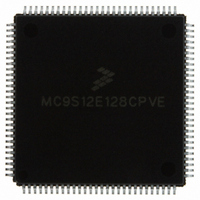
MC9S12E128CPVE Freescale Semiconductor, MC9S12E128CPVE Datasheet - Page 474

MC9S12E128CPVE
Manufacturer Part Number
MC9S12E128CPVE
Description
IC MCU 128K FLASH 25MHZ 112-LQFP
Manufacturer
Freescale Semiconductor
Series
HCS12r
Specifications of MC9S12E128CPVE
Core Processor
HCS12
Core Size
16-Bit
Speed
25MHz
Connectivity
EBI/EMI, I²C, SCI, SPI
Peripherals
POR, PWM, WDT
Number Of I /o
91
Program Memory Size
128KB (128K x 8)
Program Memory Type
FLASH
Ram Size
8K x 8
Voltage - Supply (vcc/vdd)
2.35 V ~ 2.75 V
Data Converters
A/D 16x10b; D/A 2x8b
Oscillator Type
Internal
Operating Temperature
-40°C ~ 85°C
Package / Case
112-LQFP
Processor Series
S12E
Core
HCS12
Data Bus Width
16 bit
Data Ram Size
8 KB
Interface Type
SCI/SPI
Maximum Clock Frequency
25 MHz
Number Of Programmable I/os
92
Number Of Timers
12
Operating Supply Voltage
3.135 V to 5.5 V
Maximum Operating Temperature
+ 85 C
Mounting Style
SMD/SMT
3rd Party Development Tools
EWHCS12
Minimum Operating Temperature
- 40 C
On-chip Adc
16-ch x 10-bit
On-chip Dac
2-ch x 8-bit
Controller Family/series
HCS12/S12X
No. Of I/o's
90
Ram Memory Size
8KB
Cpu Speed
25MHz
No. Of Timers
4
Embedded Interface Type
I2C, SCI, SPI
Rohs Compliant
Yes
For Use With
M68EVB912E128 - BOARD EVAL FOR MC9S12E128/64
Lead Free Status / RoHS Status
Lead free / RoHS Compliant
Eeprom Size
-
Lead Free Status / Rohs Status
Lead free / RoHS Compliant
Available stocks
Company
Part Number
Manufacturer
Quantity
Price
Company:
Part Number:
MC9S12E128CPVE
Manufacturer:
Freescale Semiconductor
Quantity:
10 000
- Current page: 474 of 606
- Download datasheet (4Mb)
Chapter 16 Debug Module (DBGV1)
The DBG in DBG mode includes these distinctive features:
474
•
•
•
•
•
•
•
Three comparators (A, B, and C)
— Dual mode, comparators A and B used to compare addresses
— Full mode, comparator A compares address and comparator B compares data
— Can be used as trigger and/or breakpoint
— Comparator C used in LOOP1 capture mode or as additional breakpoint
Four capture modes
— Normal mode, change-of-flow information is captured based on trigger specification
— Loop1 mode, comparator C is dynamically updated to prevent redundant change-of-flow
— Detail mode, address and data for all cycles except program fetch (P) and free (f) cycles are
— Profile mode, last instruction address executed by CPU is returned when trace buffer address is
Two types of breakpoint or debug triggers
— Break just before a specific instruction will begin execution (tag)
— Break on the first instruction boundary after a match occurs (force)
BDM or SWI breakpoint
— Enter BDM on breakpoint (BDM)
— Execute SWI on breakpoint (SWI)
Nine trigger modes for comparators A and B
— A
— A or B
— A then B
— A and B, where B is data (full mode)
— A and not B, where B is data (full mode)
— Event only B, store data
— A then event only B, store data
— Inside range, A address B
— Outside range, address
Comparator C provides an additional tag or force breakpoint when capture mode is not configured
in LOOP1 mode.
Sixty-four word (16 bits wide) trace buffer for storing change-of-flow information, event only data
and other bus information.
— Source address of taken conditional branches (long, short, bit-conditional, and loop constructs)
— Destination address of indexed JMP, JSR, and CALL instruction.
— Destination address of RTI, RTS, and RTC instructions
— Vector address of interrupts, except for SWI and BDM vectors
storage.
stored in trace buffer
read
MC9S12E128 Data Sheet, Rev. 1.07
or address B
Freescale Semiconductor
Related parts for MC9S12E128CPVE
Image
Part Number
Description
Manufacturer
Datasheet
Request
R
Part Number:
Description:
Manufacturer:
Freescale Semiconductor, Inc
Datasheet:
Part Number:
Description:
Manufacturer:
Freescale Semiconductor, Inc
Datasheet:
Part Number:
Description:
Manufacturer:
Freescale Semiconductor, Inc
Datasheet:
Part Number:
Description:
Manufacturer:
Freescale Semiconductor, Inc
Datasheet:
Part Number:
Description:
Manufacturer:
Freescale Semiconductor, Inc
Datasheet:
Part Number:
Description:
Manufacturer:
Freescale Semiconductor, Inc
Datasheet:
Part Number:
Description:
Manufacturer:
Freescale Semiconductor, Inc
Datasheet:
Part Number:
Description:
Manufacturer:
Freescale Semiconductor, Inc
Datasheet:
Part Number:
Description:
Manufacturer:
Freescale Semiconductor, Inc
Datasheet:
Part Number:
Description:
Manufacturer:
Freescale Semiconductor, Inc
Datasheet:
Part Number:
Description:
Manufacturer:
Freescale Semiconductor, Inc
Datasheet:
Part Number:
Description:
Manufacturer:
Freescale Semiconductor, Inc
Datasheet:
Part Number:
Description:
Manufacturer:
Freescale Semiconductor, Inc
Datasheet:
Part Number:
Description:
Manufacturer:
Freescale Semiconductor, Inc
Datasheet:
Part Number:
Description:
Manufacturer:
Freescale Semiconductor, Inc
Datasheet:


