HD64F3644PV Renesas Electronics America, HD64F3644PV Datasheet - Page 93
HD64F3644PV
Manufacturer Part Number
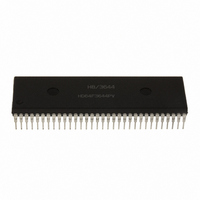
HD64F3644PV
Description
IC H8/3644 MCU FLASH 32K 64SDIP
Manufacturer
Renesas Electronics America
Series
H8® H8/300Lr
Datasheet
1.HD64F3644HV.pdf
(551 pages)
Specifications of HD64F3644PV
Core Processor
H8/300L
Core Size
8-Bit
Speed
8MHz
Connectivity
SCI
Peripherals
PWM, WDT
Number Of I /o
53
Program Memory Size
32KB (32K x 8)
Program Memory Type
FLASH
Ram Size
1K x 8
Voltage - Supply (vcc/vdd)
2.7 V ~ 5.5 V
Data Converters
A/D 8x8b
Oscillator Type
Internal
Operating Temperature
-20°C ~ 75°C
Package / Case
64-SDIP (0.750", 19.05mm)
Lead Free Status / RoHS Status
Lead free / RoHS Compliant
Eeprom Size
-
Available stocks
Company
Part Number
Manufacturer
Quantity
Price
Company:

Part Number:
HD64F3644PV
Manufacturer:
Renesas Electronics America
Quantity:
135


3.3.3
There are 12 external interrupts: IRQ
Interrupts IRQ
IRQ
depending on the settings of bits IEG3 to IEG0 in IEGR1.
When these pins are designated as pins IRQ
edge is input, the corresponding bit in IRR1 is set to 1, requesting an interrupt. Recognition of
these interrupt requests can be disabled individually by clearing bits IEN3 to IEN0 to 0 in IENR1.
These interrupts can all be masked by setting the I bit to 1 in CCR.
When IRQ
numbers 7 to 4 are assigned to interrupts IRQ
to IRQ
INT Interrupts: INT interrupts are requested by input signals to pins INT
interrupts are detected by either rising edge sensing or falling edge sensing, depending on the
settings of bits INTEG7 to INTEG0 in IEGR2.
When the designated edge is input at pins INT
requesting an interrupt. Recognition of these interrupt requests can be disabled individually by
clearing bits INTEN7 to INTEN0 to 0 in IENR3. These interrupts can all be masked by setting the
I bit to 1 in CCR.
When INT interrupt exception handling is initiated, the I bit is set to 1 in CCR. Vector number 8 is
assigned to the INT interrupts. All eight interrupts have the same vector number, so the interrupt-
handling routine must discriminate the interrupt source.
Note: Pins INT
0
. These interrupts are detected by either rising edge sensing or falling edge sensing,
3
the designated edge is input or output, the corresponding bit INTFn is set to 1.
(low). Table 3.2 gives details.
External Interrupts
3
to IRQ
3
7
to IRQ
to INT
0
interrupt exception handling is initiated, the I bit is set to 1 in CCR. Vector
0
0
: Interrupts IRQ
are multiplexed with port 5. Even in port usage of these pins, whenever
3
to IRQ
3
to IRQ
3
to IRQ
0
3
7
and INT
to IRQ
to INT
0
are requested by input signals to pins IRQ
0
in port mode register 1 and the designated
0
0
. The order of priority is from IRQ
7
, the corresponding bit in IRR3 is set to 1,
to INT
Rev. 6.00 Sep 12, 2006 page 71 of 526
0
.
Section 3 Exception Handling
7
to INT
REJ09B0326-0600
0
. These
0
(high)
3
to
Related parts for HD64F3644PV
Image
Part Number
Description
Manufacturer
Datasheet
Request
R

Part Number:
Description:
(HD64 Series) Hitachi Single-Chip Microcomputer
Manufacturer:
Hitachi Semiconductor
Datasheet:

Part Number:
Description:
KIT STARTER FOR M16C/29
Manufacturer:
Renesas Electronics America
Datasheet:

Part Number:
Description:
KIT STARTER FOR R8C/2D
Manufacturer:
Renesas Electronics America
Datasheet:

Part Number:
Description:
R0K33062P STARTER KIT
Manufacturer:
Renesas Electronics America
Datasheet:

Part Number:
Description:
KIT STARTER FOR R8C/23 E8A
Manufacturer:
Renesas Electronics America
Datasheet:

Part Number:
Description:
KIT STARTER FOR R8C/25
Manufacturer:
Renesas Electronics America
Datasheet:

Part Number:
Description:
KIT STARTER H8S2456 SHARPE DSPLY
Manufacturer:
Renesas Electronics America
Datasheet:

Part Number:
Description:
KIT STARTER FOR R8C38C
Manufacturer:
Renesas Electronics America
Datasheet:

Part Number:
Description:
KIT STARTER FOR R8C35C
Manufacturer:
Renesas Electronics America
Datasheet:

Part Number:
Description:
KIT STARTER FOR R8CL3AC+LCD APPS
Manufacturer:
Renesas Electronics America
Datasheet:
Part Number:
Description:
KIT STARTER FOR RX610
Manufacturer:
Renesas Electronics America
Datasheet:

Part Number:
Description:
KIT STARTER FOR R32C/118
Manufacturer:
Renesas Electronics America
Datasheet:

Part Number:
Description:
KIT DEV RSK-R8C/26-29
Manufacturer:
Renesas Electronics America
Datasheet:

Part Number:
Description:
KIT STARTER FOR SH7124
Manufacturer:
Renesas Electronics America
Datasheet:

Part Number:
Description:
KIT STARTER FOR H8SX/1622
Manufacturer:
Renesas Electronics America
Datasheet: