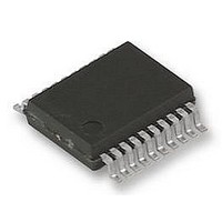
UPD78F9222MC(T)-5A4-A NEC, UPD78F9222MC(T)-5A4-A Datasheet - Page 165

UPD78F9222MC(T)-5A4-A
Manufacturer Part Number
UPD78F9222MC(T)-5A4-A
Description
8BIT MCU, 4K FLASH, 256B RAM, 78F9222
Manufacturer
NEC
Datasheet
1.UPD78F9222MCT-5A4-A.pdf
(414 pages)
Specifications of UPD78F9222MC(T)-5A4-A
Controller Family/series
UPD78
No. Of I/o's
17
Ram Memory Size
256Byte
Cpu Speed
10MHz
No. Of Timers
4
No. Of
RoHS Compliant
Core Size
8bit
Program Memory Size
4KB
Oscillator Type
External, Internal
Available stocks
Company
Part Number
Manufacturer
Quantity
Price
Company:
Part Number:
UPD78F9222MC(T)-5A4-A
Manufacturer:
NEC
Quantity:
1 000
Company:
Part Number:
UPD78F9222MC(T)-5A4-A
Manufacturer:
NEC/PBF
Quantity:
6 640
Part Number:
UPD78F9222MC(T)-5A4-A
Manufacturer:
RENESAS/瑞萨
Quantity:
20 000
- Current page: 165 of 414
- Download datasheet (4Mb)
<R>
Note The time from the rising of the ADCE bit to the rising of the ADCS bit must be 1
Caution
Notes
internal circuit.
ADCS
1. The above sampling time and conversion time do not include the clock frequency error.
Comparator
0
0
1
Select the sampling time and conversion time such that Notes 2 and 3 above are satisfied,
while taking the clock frequency error into consideration (an error margin maximum of ±5%
when using the high-speed internal oscillator).
2. Be sure to set the FR2, FR1, and FR0, in accordance with the reference voltage so that Notes 2
3. Set the sampling time as follows.
4. Set the A/D conversion time as follows.
5. Setting is prohibited because the values do not satisfy the condition of Notes 3 or 4.
6. The operation of the comparator is controlled by ADCS and ADCE, and it takes 1
and 3 below are satisfied.
Example When AV
• AV
• AV
• AV
• AV
• AV
• AV
• AV
• AV
operation start to operation stabilization. Therefore, when ADCS is set to 1 after 1
has elapsed from the time ADCE is set to 1, the conversion result at that time has priority over
the first conversion result. If the ADCS is set to 1 without waiting for 1
first conversion data.
ADCE
ADCS
ADCE
REF
REF
REF
REF
REF
REF
REF
REF
0
1
×
≥ 4.5 V:
≥ 4.0 V:
≥ 2.85 V: 3.0
≥ 2.7 V:
≥ 4.5 V:
≥ 4.0 V:
≥ 2.85 V: 6.0
≥ 2.7 V:
Figure 10-4. Timing Chart When Comparator Is Used
• The sampling time is 11.0
• Set FR2, FR1, and FR0 = 0, 1, 1 or 1, 1, 1.
Note
more and 100
Stop status (DC power consumption path does not exist)
Conversion waiting mode (only comparator consumes power)
Conversion mode
Table 10-2. Settings of ADCS and ADCE
Conversion
operation
1.0
2.4
11.0
3.0
4.8
14.0
REF
CHAPTER 10 A/D CONVERTER
µ
µ
µ
µ
µ
µ
≥ 2.7 V, f
s or more
s or more
s or more
µ
s or more and less than 100
s or more and less than 100
s or more and less than 100
µ
Comparator operating
User’s Manual U16898EJ5V0UD
s or more
s or more and less than 100
µ
s or less.
Conversion
XP
waiting
= 8 MHz
A/D Conversion Operation
µ
s or more and the A/D conversion time is 14.0
Conversion
operation
µ
µ
µ
µ
s
s
s
s
Conversion stopped
µ
s or longer to stabilize the
µ
s or longer, ignore the
µ
s or more
µ
s from
µ
165
s or
Related parts for UPD78F9222MC(T)-5A4-A
Image
Part Number
Description
Manufacturer
Datasheet
Request
R

Part Number:
Description:
16/8 bit single-chip microcomputer
Manufacturer:
NEC
Datasheet:

Part Number:
Description:
Dual audio power amp circuit
Manufacturer:
NEC
Datasheet:

Part Number:
Description:
Dual comparator
Manufacturer:
NEC
Datasheet:

Part Number:
Description:
MOS type composite field effect transistor
Manufacturer:
NEC
Datasheet:

Part Number:
Description:
50 V/100 mA FET array incorporating 2 N-ch MOSFETs
Manufacturer:
NEC
Datasheet:

Part Number:
Description:
6-pin small MM high-frequency double transistor
Manufacturer:
NEC
Datasheet:

Part Number:
Description:
6-pin small MM high-frequency double transistor
Manufacturer:
NEC
Datasheet:

Part Number:
Description:
6-pin small MM high-frequency double transistor
Manufacturer:
NEC
Datasheet:

Part Number:
Description:
6-pin small MM high-frequency double transistor
Manufacturer:
NEC
Datasheet:

Part Number:
Description:
Twin transistors equipped with different model chips(6P small MM)
Manufacturer:
NEC
Datasheet:

Part Number:
Description:
Bipolar analog integrated circuit
Manufacturer:
NEC
Datasheet:


