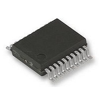
UPD78F9222MC(T)-5A4-A NEC, UPD78F9222MC(T)-5A4-A Datasheet - Page 396

UPD78F9222MC(T)-5A4-A
Manufacturer Part Number
UPD78F9222MC(T)-5A4-A
Description
8BIT MCU, 4K FLASH, 256B RAM, 78F9222
Manufacturer
NEC
Datasheet
1.UPD78F9222MCT-5A4-A.pdf
(414 pages)
Specifications of UPD78F9222MC(T)-5A4-A
Controller Family/series
UPD78
No. Of I/o's
17
Ram Memory Size
256Byte
Cpu Speed
10MHz
No. Of Timers
4
No. Of
RoHS Compliant
Core Size
8bit
Program Memory Size
4KB
Oscillator Type
External, Internal
Available stocks
Company
Part Number
Manufacturer
Quantity
Price
Company:
Part Number:
UPD78F9222MC(T)-5A4-A
Manufacturer:
NEC
Quantity:
1 000
Company:
Part Number:
UPD78F9222MC(T)-5A4-A
Manufacturer:
NEC/PBF
Quantity:
6 640
Part Number:
UPD78F9222MC(T)-5A4-A
Manufacturer:
RENESAS/瑞萨
Quantity:
20 000
- Current page: 396 of 414
- Download datasheet (4Mb)
396
Serial
interface
UART6
Interrupt
functions
Standby
function
Function
Permissible
baud rate range
during
reception
Vector table
address
IF0, IF1:
Interrupt
request flag
registers,
MK0, MK1:
Interrupt mask
flag registers
INTM0:
External
interrupt mode
register 0
INTM1:
External
interrupt mode
register 1
Interrupt
requests are
held pending
Interrupt
request
pending
STOP mode
STOP mode,
HALT mode
STOP mode
OSTS:
Oscillation
stabilization
time select
register
Details of
Function
−
Make sure that the baud rate error during reception is within the permissible
error range, by using the calculation expression shown below.
No interrupt sources correspond to the vector table address 0014H.
Because P30, P31, P41, and P43 have an alternate function as external
interrupt inputs, when the output level is changed by specifying the output mode
of the port function, an interrupt request flag is set. Therefore, the interrupt
mask flag should be set to 1 before using the output mode.
Be sure to clear bits 0 and 1 to 0.
Before setting the INTM0 register, be sure to set the corresponding interrupt
mask flag (××MK× = 1) to disable interrupts. After setting the INTM0 register,
clear the interrupt request flag (××IF× = 0), then clear the interrupt mask flag
(××MK× = 0), which will enable interrupts.
Be sure to clear bits 2 to 7 to 0.
Before setting INTM1, set PMK3 to 1 to disable interrupts.
To enable interrupts, clear PIF3 to 0, then clear PMK3 to 0.
Interrupt requests will be held pending while the interrupt request flag registers
(IF0, IF1) or interrupt mask flag registers (MK0, MK1) are being accessed.
Multiple interrupts can be acknowledged even for low-priority interrupts.
The LSRSTOP setting is valid only when “Can be stopped by software” is set for
the low-speed internal oscillator by the option byte.
When shifting to the STOP mode, be sure to stop the peripheral hardware
operation before executing STOP instruction (except the peripheral hardware
that operates on the low-speed internal oscillation clock).
The following sequence is recommended for operating current reduction of the
A/D converter when the standby function is used: First clear bit 7 (ADCS) and
bit 0 (ADCE) of the A/D converter mode register (ADM) to 0 to stop the A/D
conversion operation, and then execute the HALT or STOP instruction.
If the low-speed internal oscillator is operating before the STOP mode is set,
oscillation of the low-speed internal oscillation clock cannot be stopped in the
STOP mode (refer to Table 13-1).
To set and then release the STOP mode, set the oscillation stabilization time as
follows. Expected oscillation stabilization time of resonator ≤ Oscillation
stabilization time set by OSTS
APPENDIX D LIST OF CAUTIONS
User’s Manual U16898EJ5V0UD
Cautions
p. 214
p. 218
pp. 221,
222
p. 223
p. 223
p. 224
p. 224
p. 227
p. 228
p. 230
p. 231
p. 231
p. 231
p. 232
Page
(13/19)
Related parts for UPD78F9222MC(T)-5A4-A
Image
Part Number
Description
Manufacturer
Datasheet
Request
R

Part Number:
Description:
16/8 bit single-chip microcomputer
Manufacturer:
NEC
Datasheet:

Part Number:
Description:
Dual audio power amp circuit
Manufacturer:
NEC
Datasheet:

Part Number:
Description:
Dual comparator
Manufacturer:
NEC
Datasheet:

Part Number:
Description:
MOS type composite field effect transistor
Manufacturer:
NEC
Datasheet:

Part Number:
Description:
50 V/100 mA FET array incorporating 2 N-ch MOSFETs
Manufacturer:
NEC
Datasheet:

Part Number:
Description:
6-pin small MM high-frequency double transistor
Manufacturer:
NEC
Datasheet:

Part Number:
Description:
6-pin small MM high-frequency double transistor
Manufacturer:
NEC
Datasheet:

Part Number:
Description:
6-pin small MM high-frequency double transistor
Manufacturer:
NEC
Datasheet:

Part Number:
Description:
6-pin small MM high-frequency double transistor
Manufacturer:
NEC
Datasheet:

Part Number:
Description:
Twin transistors equipped with different model chips(6P small MM)
Manufacturer:
NEC
Datasheet:

Part Number:
Description:
Bipolar analog integrated circuit
Manufacturer:
NEC
Datasheet:


