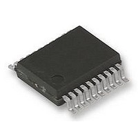
UPD78F9222MC(T)-5A4-A NEC, UPD78F9222MC(T)-5A4-A Datasheet - Page 324

UPD78F9222MC(T)-5A4-A
Manufacturer Part Number
UPD78F9222MC(T)-5A4-A
Description
8BIT MCU, 4K FLASH, 256B RAM, 78F9222
Manufacturer
NEC
Datasheet
1.UPD78F9222MCT-5A4-A.pdf
(414 pages)
Specifications of UPD78F9222MC(T)-5A4-A
Controller Family/series
UPD78
No. Of I/o's
17
Ram Memory Size
256Byte
Cpu Speed
10MHz
No. Of Timers
4
No. Of
RoHS Compliant
Core Size
8bit
Program Memory Size
4KB
Oscillator Type
External, Internal
Available stocks
Company
Part Number
Manufacturer
Quantity
Price
Company:
Part Number:
UPD78F9222MC(T)-5A4-A
Manufacturer:
NEC
Quantity:
1 000
Company:
Part Number:
UPD78F9222MC(T)-5A4-A
Manufacturer:
NEC/PBF
Quantity:
6 640
Part Number:
UPD78F9222MC(T)-5A4-A
Manufacturer:
RENESAS/瑞萨
Quantity:
20 000
- Current page: 324 of 414
- Download datasheet (4Mb)
<R>
19.1 Connecting QB-MINI2 to 78K0S/KA1+
on-chip debug emulator (QB-MINI2).
324
The 78K0S/KA1+ uses RESET, X1, X2, INTP3, V
Caution
Notes 1. The RESET pin is used to download the monitor program at debugger startup or to implement
Caution The constants described in the circuit connection example are reference values. If you
Do not use the on-chip debug function in products designated for mass production, because the
guaranteed number of rewritable times of the flash memory may be exceeded when this function
is used, and product reliability therefore cannot be guaranteed. NEC Electronics is not liable for
problems occurring when the on-chip debug function is used.
Target connector
2. This is the pin connection when the X1 and X2 pins are not used in the target system. When using
3. No problem will occur if the dashed line portions are connected.
4. This pin is connected to enhance the accuracy of time measurement between run and break during
RESET_OUT
forced reset. Therefore, a pin that alternately functions as the RESET pin cannot be used. For
reset pin connection, refer to QB-MINI2 User’s Manual (U18371E).
the X1 and X2 pins, refer to 19.1.2 Connection of X1 and X2 pins.
debugging. Debugging is possible even if this pin is left open, but measurement error occurs in
several ms units.
RESET_IN
H/S
R.F.U.
R.F.U.
R.F.U.
R.F.U.
R.F.U.
R.F.U.
DATA
DATA
Note 4
GND
INTP
CLK
CLK
perform flash programming aiming at mass production, thoroughly evaluate whether
the specifications of the target device are satisfied.
V
DD
1
2
3
4
5
6
7
8
9
10
11
12
13
14
15
16
CHAPTER 19 ON-CHIP DEBUG FUNCTION
Figure 19-1. Recommended Circuit Connection
V
DD
User’s Manual U16898EJ5V0UD
Note 3
Note 3
DD
, and GND pins to communicate with the host machine via an
10 kΩ
V
V
V
DD
DD
DD
3 to 10 kΩ
1 kΩ
1 kΩ
1 to 10 kΩ
RESET
X2
X1
INTP3
Target device
RESET signal
Note 2
Note 2
Reset circuit
Note 5
Note 1
GND
V
DD
V
DD
Related parts for UPD78F9222MC(T)-5A4-A
Image
Part Number
Description
Manufacturer
Datasheet
Request
R

Part Number:
Description:
16/8 bit single-chip microcomputer
Manufacturer:
NEC
Datasheet:

Part Number:
Description:
Dual audio power amp circuit
Manufacturer:
NEC
Datasheet:

Part Number:
Description:
Dual comparator
Manufacturer:
NEC
Datasheet:

Part Number:
Description:
MOS type composite field effect transistor
Manufacturer:
NEC
Datasheet:

Part Number:
Description:
50 V/100 mA FET array incorporating 2 N-ch MOSFETs
Manufacturer:
NEC
Datasheet:

Part Number:
Description:
6-pin small MM high-frequency double transistor
Manufacturer:
NEC
Datasheet:

Part Number:
Description:
6-pin small MM high-frequency double transistor
Manufacturer:
NEC
Datasheet:

Part Number:
Description:
6-pin small MM high-frequency double transistor
Manufacturer:
NEC
Datasheet:

Part Number:
Description:
6-pin small MM high-frequency double transistor
Manufacturer:
NEC
Datasheet:

Part Number:
Description:
Twin transistors equipped with different model chips(6P small MM)
Manufacturer:
NEC
Datasheet:

Part Number:
Description:
Bipolar analog integrated circuit
Manufacturer:
NEC
Datasheet:


