DO-CPLD-DK-G Xilinx Inc, DO-CPLD-DK-G Datasheet - Page 122
DO-CPLD-DK-G
Manufacturer Part Number
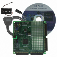
DO-CPLD-DK-G
Description
KIT DESIGN CPLD W/BATT HOLDER
Manufacturer
Xilinx Inc
Series
CoolRunner™- IIr
Type
CPLDr
Specifications of DO-CPLD-DK-G
Contents
Proto Board, Download Cable, Samples, Software
For Use With/related Products
CoolRunner-ll, XC9500XL
Lead Free Status / RoHS Status
Lead free / RoHS Compliant
Other names
122-1512
Available stocks
Company
Part Number
Manufacturer
Quantity
Price


Chapter 6: Implementing FPGA Designs
FPGA Reports
112
18. When there is a green tick next to Translate, Map, and Place and Route, your
Each stage has its own report. Clicking on the “+” next to each stage lists the reports
available:
•
•
•
•
•
•
•
•
WebPACK ISE software has additional tools for complex timing analysis and floor
planning, which are beyond the scope of this introductory book. To find out more about
advanced software tools, visit the software documentation page at our website:
http://www.xilinx.com/support/software_manuals.htm
design has completed the implementation stage.
A green tick means that the design ran through without any warnings. A yellow
exclamation point may mean that there is a warning in one of the reports. If you’ve
followed the design procedure outlined in this example, there should be no errors or
warnings.
The Translate Report shows any errors in the design or the UCF.
The Map Report confirms the resources used within the device and describes trimmed
and merged logic. It will also describe exactly where each portion of the design is
located in the actual device. A detailed Map Report can be chosen in the Properties for
map.
The Post-Map Static Timing Report shows the logic delays only (no routing) covered
by the timing constraints. This design has two timing constraints, the clock period and
the clock-to-out time of the three lights. If the logic-only delays don’t meet timing
constraints, the additional delay added by routing will only add to the problem.
Without a routing delay, these traffic lights would run at 216 MHz!
The Place and Route Report gives a step-by-step progress report. The place and route
tool must be aware of timing requirements. It will list the given constraints and report
how comfortably the design fell within – or how much it failed – the constraints.
The Asynchronous Delay Report is concerned with the worst path delays in the
design – both logic and routing.
The Pad Report displays the final pin-out of the design, with information regarding
the drive strength and signalling standard.
The Guide Report shows how well a guide file has been met (if one was specified).
The Post Place and Route Static Timing Report adds the routing delays. Notice that
the max frequency of the clock has dropped.
Figure 6-14: Completed Implementation
www.xilinx.com
Programmable Logic Design
June 12, 2006
R
Related parts for DO-CPLD-DK-G
Image
Part Number
Description
Manufacturer
Datasheet
Request
R

Part Number:
Description:
STARTER KIT CPLD
Manufacturer:
Xilinx Inc
Datasheet:
Part Number:
Description:
KIT STARTER CPLD JAPANESE
Manufacturer:
Xilinx Inc
Datasheet:
Part Number:
Description:
KIT STARTER CPLD-JAPANESE
Manufacturer:
Xilinx Inc
Datasheet:

Part Number:
Description:
IC CPLD .8K 36MCELL 44-VQFP
Manufacturer:
Xilinx Inc
Datasheet:

Part Number:
Description:
IC CPLD 72MCRCELL 10NS 44VQFP
Manufacturer:
Xilinx Inc
Datasheet:

Part Number:
Description:
IC CPLD 1.6K 72MCELL 64-VQFP
Manufacturer:
Xilinx Inc
Datasheet:

Part Number:
Description:
IC CR-II CPLD 64MCELL 44-VQFP
Manufacturer:
Xilinx Inc
Datasheet:

Part Number:
Description:
IC CPLD 1.6K 72MCELL 100-TQFP
Manufacturer:
Xilinx Inc
Datasheet:

Part Number:
Description:
IC CR-II CPLD 64MCELL 56-BGA
Manufacturer:
Xilinx Inc
Datasheet:

Part Number:
Description:
IC CPLD 72MCRCELL 7.5NS 44VQFP
Manufacturer:
Xilinx Inc
Datasheet:
Part Number:
Description:
IC CR-II CPLD 64MCELL 100-VQFP
Manufacturer:
Xilinx Inc
Datasheet:
Part Number:
Description:
IC CPLD 1.6K 72MCELL 100-TQFP
Manufacturer:
Xilinx Inc
Datasheet:

Part Number:
Description:
IC CPLD 72MCRCELL 7.5NS 64VQFP
Manufacturer:
Xilinx Inc
Datasheet:
Part Number:
Description:
IC CPLD 1.6K 72MCELL 100-TQFP
Manufacturer:
Xilinx Inc
Datasheet:

Part Number:
Description:
IC CPLD 1.5K 64MCELL HP 44-VQFP
Manufacturer:
Xilinx Inc