DO-CPLD-DK-G Xilinx Inc, DO-CPLD-DK-G Datasheet - Page 49
DO-CPLD-DK-G
Manufacturer Part Number
DO-CPLD-DK-G
Description
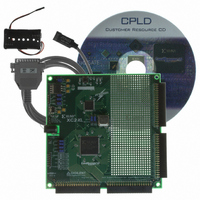
KIT DESIGN CPLD W/BATT HOLDER
Manufacturer
Xilinx Inc
Series
CoolRunner™- IIr
Type
CPLDr
Specifications of DO-CPLD-DK-G
Contents
Proto Board, Download Cable, Samples, Software
For Use With/related Products
CoolRunner-ll, XC9500XL
Lead Free Status / RoHS Status
Lead free / RoHS Compliant
Other names
122-1512
Available stocks
Company
Part Number
Manufacturer
Quantity
Price


HDL Design Process
Programmable Logic Design
June 12, 2006
R
EDIF is the industry-wide standard for netlists; many others exist, including vendor-
specific ones such as the Xilinx Netlist Format (XNF). Once you have the design netlist, you
have all you need to determine what the circuit does.
The example on the previous pages is obviously very simplistic. Let’s describe a more
realistic design of 10,000 equivalent gates. The typical schematic page contains about 200
gates, contained with soft macros. Therefore, it would require 50 schematic pages to create
a 10,000-gate design! Each page needs to go through all the steps mentioned previously:
adding components, interconnecting the gates, adding I/Os, and generating a netlist. This
is rather time-consuming, especially if you want to have a 20,000, 50,000, or even larger
design.
Another inherent problem with using schematic capture is the difficulty in migrating
between vendors and technologies. If you initially create your 10,000- gate design with
FPGA vendor X and then want to migrate to a gate array, you would have to modify every
one of those 50 pages using the gate array vendor’s component library.
There has to be a better way, and, of course, there is. It is called high-level design (HLD),
behavioral, or hardware description language (HDL). For our purposes, these three terms
are essentially the same thing. The idea is to use a high-level language to describe the
circuit in a text file rather than a graphical low-level gate description. The term behavioral is
used because in this powerful language you describe the function or behavior of the circuit
in words rather than figuring out the appropriate gates needed to create the application.
There are two major flavors of HDL: VHDL and Verilog.
As an example, consider the design work needed specifying a 16 x 16 multiplier with
schematic capture or an HDL file. A multiplier is a regular but complex arrangement of
adders and registers that requires quite a few gates. Our example has two 16-bit inputs (A
and B) and a 32-bit product output (Y = A x B) – for a total of 64 I/Os. This circuit requires
approximately 6,000 equivalent gates. In the schematic implementation, the required gates
Design Flow
Schematic
Capture
Specification
Libraries
Netlist
Figure 3-2: Design Specification – Netlist
www.xilinx.com
clock
reset
101010101001110101010101
010101011110001110100111
101010101001110101010101
010101011110001110100111
101010101001110101010101
010101011110001110100111
101010101001110101010101
010101011110001110100111
CLOCK
RESET
Design Schematic
Counter
Design Netlist
COUNT (3.0)
CLK
RESET
TIME (3.0)
STAT_MAC
HDL Design Process
AUG
GRN
RG
amber_light
green_light
red_light
39
Related parts for DO-CPLD-DK-G
Image
Part Number
Description
Manufacturer
Datasheet
Request
R

Part Number:
Description:
STARTER KIT CPLD
Manufacturer:
Xilinx Inc
Datasheet:
Part Number:
Description:
KIT STARTER CPLD JAPANESE
Manufacturer:
Xilinx Inc
Datasheet:
Part Number:
Description:
KIT STARTER CPLD-JAPANESE
Manufacturer:
Xilinx Inc
Datasheet:

Part Number:
Description:
IC CPLD .8K 36MCELL 44-VQFP
Manufacturer:
Xilinx Inc
Datasheet:

Part Number:
Description:
IC CPLD 72MCRCELL 10NS 44VQFP
Manufacturer:
Xilinx Inc
Datasheet:

Part Number:
Description:
IC CPLD 1.6K 72MCELL 64-VQFP
Manufacturer:
Xilinx Inc
Datasheet:

Part Number:
Description:
IC CR-II CPLD 64MCELL 44-VQFP
Manufacturer:
Xilinx Inc
Datasheet:

Part Number:
Description:
IC CPLD 1.6K 72MCELL 100-TQFP
Manufacturer:
Xilinx Inc
Datasheet:

Part Number:
Description:
IC CR-II CPLD 64MCELL 56-BGA
Manufacturer:
Xilinx Inc
Datasheet:

Part Number:
Description:
IC CPLD 72MCRCELL 7.5NS 44VQFP
Manufacturer:
Xilinx Inc
Datasheet:
Part Number:
Description:
IC CR-II CPLD 64MCELL 100-VQFP
Manufacturer:
Xilinx Inc
Datasheet:
Part Number:
Description:
IC CPLD 1.6K 72MCELL 100-TQFP
Manufacturer:
Xilinx Inc
Datasheet:

Part Number:
Description:
IC CPLD 72MCRCELL 7.5NS 64VQFP
Manufacturer:
Xilinx Inc
Datasheet:
Part Number:
Description:
IC CPLD 1.6K 72MCELL 100-TQFP
Manufacturer:
Xilinx Inc
Datasheet:

Part Number:
Description:
IC CPLD 1.5K 64MCELL HP 44-VQFP
Manufacturer:
Xilinx Inc