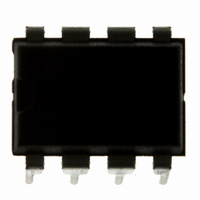
MC9S08QG4MPAE Freescale Semiconductor, MC9S08QG4MPAE Datasheet - Page 111

MC9S08QG4MPAE
Manufacturer Part Number
MC9S08QG4MPAE
Description
IC MCU 4K FLASH 8-PDIP
Manufacturer
Freescale Semiconductor
Series
HCS08r
Datasheet
1.MC9S08QG8CDTER.pdf
(314 pages)
Specifications of MC9S08QG4MPAE
Core Processor
HCS08
Core Size
8-Bit
Speed
20MHz
Connectivity
I²C, SCI, SPI
Peripherals
LVD, POR, PWM, WDT
Number Of I /o
4
Program Memory Size
4KB (4K x 8)
Program Memory Type
FLASH
Ram Size
256 x 8
Voltage - Supply (vcc/vdd)
1.8 V ~ 3.6 V
Data Converters
A/D 4x10b
Oscillator Type
Internal
Operating Temperature
-40°C ~ 125°C
Package / Case
8-DIP (0.300", 7.62mm)
Controller Family/series
HCS08
No. Of I/o's
6
Ram Memory Size
256Byte
Cpu Speed
20MHz
No. Of Timers
2
Embedded Interface Type
I2C, SCI, SPI
Rohs Compliant
Yes
Processor Series
S08QG
Core
HCS08
Data Bus Width
8 bit
Data Ram Size
256 B
Interface Type
I2C, SCI, SPI
Maximum Clock Frequency
20 MHz
Number Of Programmable I/os
12
Number Of Timers
1
Maximum Operating Temperature
+ 125 C
Mounting Style
Through Hole
3rd Party Development Tools
EWS08
Development Tools By Supplier
DEMO9S08QG8E
Minimum Operating Temperature
- 40 C
On-chip Adc
10 bit, 8 Channel
Lead Free Status / RoHS Status
Lead free / RoHS Compliant
Eeprom Size
-
Lead Free Status / Rohs Status
Details
- Current page: 111 of 314
- Download datasheet (6Mb)
8.1.3
The ACMP has the following features:
8.1.4
This section defines the ACMP operation in wait, stop, and background debug modes.
8.1.4.1
The ACMP continues to run in wait mode if enabled before executing the WAIT instruction. Therefore,
the ACMP can be used to bring the MCU out of wait mode if the ACMP interrupt, ACIE, is enabled. For
lowest possible current consumption, the ACMP should be disabled by software if not required as an
interrupt source during wait mode.
8.1.4.2
The ACMP is disabled in all stop modes, regardless of the settings before executing the STOP instruction.
Therefore, the ACMP cannot be used as a wake up source from stop modes.
During either stop1 or stop2 mode, the ACMP module will be fully powered down. Upon wake-up from
stop1 or stop2 mode, the ACMP module will be in the reset state.
During stop3 mode, clocks to the ACMP module are halted. No registers are affected. In addition, the
ACMP comparator circuit will enter a low power state. No compare operation will occur while in stop3.
If stop3 is exited with a reset, the ACMP will be put into its reset state. If stop3 is exited with an interrupt,
the ACMP continues from the state it was in when stop3 was entered.
8.1.4.3
When the microcontroller is in active background mode, the ACMP will continue to operate normally.
8.1.5
The block diagram for the analog comparator module is shown
Freescale Semiconductor
•
•
•
•
•
•
Full rail-to-rail supply operation.
Less than 40 mV of input offset.
Less than 15 mV of hysteresis.
Selectable interrupt on rising edge, falling edge, or either rising or falling edges of comparator
output.
Option to compare to fixed internal bandgap reference voltage.
Option to allow comparator output to be visible on a pin, ACMPO.
Features
Modes of Operation
Block Diagram
ACMP in Wait Mode
ACMP in Stop Modes
ACMP in Active Background Mode
MC9S08QG8 and MC9S08QG4 Data Sheet, Rev. 5
Figure
8-2.
Analog Comparator (S08ACMPV2)
109
Related parts for MC9S08QG4MPAE
Image
Part Number
Description
Manufacturer
Datasheet
Request
R
Part Number:
Description:
Manufacturer:
Freescale Semiconductor, Inc
Datasheet:
Part Number:
Description:
Manufacturer:
Freescale Semiconductor, Inc
Datasheet:
Part Number:
Description:
Manufacturer:
Freescale Semiconductor, Inc
Datasheet:
Part Number:
Description:
Manufacturer:
Freescale Semiconductor, Inc
Datasheet:
Part Number:
Description:
Manufacturer:
Freescale Semiconductor, Inc
Datasheet:
Part Number:
Description:
Manufacturer:
Freescale Semiconductor, Inc
Datasheet:
Part Number:
Description:
Manufacturer:
Freescale Semiconductor, Inc
Datasheet:
Part Number:
Description:
Manufacturer:
Freescale Semiconductor, Inc
Datasheet:
Part Number:
Description:
Manufacturer:
Freescale Semiconductor, Inc
Datasheet:
Part Number:
Description:
Manufacturer:
Freescale Semiconductor, Inc
Datasheet:
Part Number:
Description:
Manufacturer:
Freescale Semiconductor, Inc
Datasheet:
Part Number:
Description:
Manufacturer:
Freescale Semiconductor, Inc
Datasheet:
Part Number:
Description:
Manufacturer:
Freescale Semiconductor, Inc
Datasheet:
Part Number:
Description:
Manufacturer:
Freescale Semiconductor, Inc
Datasheet:
Part Number:
Description:
Manufacturer:
Freescale Semiconductor, Inc
Datasheet:


