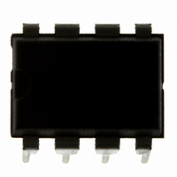
MC9S08QG4MPAE Freescale Semiconductor, MC9S08QG4MPAE Datasheet - Page 124

MC9S08QG4MPAE
Manufacturer Part Number
MC9S08QG4MPAE
Description
IC MCU 4K FLASH 8-PDIP
Manufacturer
Freescale Semiconductor
Series
HCS08r
Datasheet
1.MC9S08QG8CDTER.pdf
(314 pages)
Specifications of MC9S08QG4MPAE
Core Processor
HCS08
Core Size
8-Bit
Speed
20MHz
Connectivity
I²C, SCI, SPI
Peripherals
LVD, POR, PWM, WDT
Number Of I /o
4
Program Memory Size
4KB (4K x 8)
Program Memory Type
FLASH
Ram Size
256 x 8
Voltage - Supply (vcc/vdd)
1.8 V ~ 3.6 V
Data Converters
A/D 4x10b
Oscillator Type
Internal
Operating Temperature
-40°C ~ 125°C
Package / Case
8-DIP (0.300", 7.62mm)
Controller Family/series
HCS08
No. Of I/o's
6
Ram Memory Size
256Byte
Cpu Speed
20MHz
No. Of Timers
2
Embedded Interface Type
I2C, SCI, SPI
Rohs Compliant
Yes
Processor Series
S08QG
Core
HCS08
Data Bus Width
8 bit
Data Ram Size
256 B
Interface Type
I2C, SCI, SPI
Maximum Clock Frequency
20 MHz
Number Of Programmable I/os
12
Number Of Timers
1
Maximum Operating Temperature
+ 125 C
Mounting Style
Through Hole
3rd Party Development Tools
EWS08
Development Tools By Supplier
DEMO9S08QG8E
Minimum Operating Temperature
- 40 C
On-chip Adc
10 bit, 8 Channel
Lead Free Status / RoHS Status
Lead free / RoHS Compliant
Eeprom Size
-
Lead Free Status / Rohs Status
Details
- Current page: 124 of 314
- Download datasheet (6Mb)
Analog-to-Digital Converter (S08ADC10V1)
122
COCO
ADCO
ADCH
Field
AIEN
4:0
7
6
5
Reset:
W
R
Conversion Complete Flag — The COCO flag is a read-only bit which is set each time a conversion is
completed when the compare function is disabled (ACFE = 0). When the compare function is enabled (ACFE =
1) the COCO flag is set upon completion of a conversion only if the compare result is true. This bit is cleared
whenever ADCSC1 is written or whenever ADCRL is read.
0 Conversion not completed
1 Conversion completed
Interrupt Enable — AIEN is used to enable conversion complete interrupts. When COCO becomes set while
AIEN is high, an interrupt is asserted.
0 Conversion complete interrupt disabled
1 Conversion complete interrupt enabled
Continuous Conversion Enable — ADCO is used to enable continuous conversions.
0 One conversion following a write to the ADCSC1 when software triggered operation is selected, or one
1 Continuous conversions initiated following a write to ADCSC1 when software triggered operation is selected.
Input Channel Select — The ADCH bits form a 5-bit field which is used to select one of the input channels. The
input channels are detailed in
The successive approximation converter subsystem is turned off when the channel select bits are all set to 1.
This feature allows for explicit disabling of the ADC and isolation of the input channel from all sources.
Terminating continuous conversions this way will prevent an additional, single conversion from being performed.
It is not necessary to set the channel select bits to all 1s to place the ADC in a low-power state when continuous
conversions are not enabled because the module automatically enters a low-power state when a conversion
completes.
conversion following assertion of ADHWT when hardware triggered operation is selected.
Continuous conversions are initiated by an ADHWT event when hardware triggered operation is selected.
COCO
7
0
ADCH
00000
00001
00010
00011
00100
00101
00110
= Unimplemented or Reserved
AIEN
Figure 9-3. Status and Control Register (ADCSC1)
0
6
Table 9-3. ADCSC1 Register Field Descriptions
MC9S08QG8 and MC9S08QG4 Data Sheet, Rev. 5
Figure 9-4. Input Channel Select
Figure
ADCO
Input Select
0
5
AD0
AD1
AD2
AD3
AD4
AD5
AD6
9-4.
1
4
Description
1
3
ADCH
ADCH
10000
10001
10010
10011
10100
10101
10110
1
2
Freescale Semiconductor
1
1
Input Select
AD16
AD17
AD18
AD19
AD20
AD21
AD22
1
0
Related parts for MC9S08QG4MPAE
Image
Part Number
Description
Manufacturer
Datasheet
Request
R
Part Number:
Description:
Manufacturer:
Freescale Semiconductor, Inc
Datasheet:
Part Number:
Description:
Manufacturer:
Freescale Semiconductor, Inc
Datasheet:
Part Number:
Description:
Manufacturer:
Freescale Semiconductor, Inc
Datasheet:
Part Number:
Description:
Manufacturer:
Freescale Semiconductor, Inc
Datasheet:
Part Number:
Description:
Manufacturer:
Freescale Semiconductor, Inc
Datasheet:
Part Number:
Description:
Manufacturer:
Freescale Semiconductor, Inc
Datasheet:
Part Number:
Description:
Manufacturer:
Freescale Semiconductor, Inc
Datasheet:
Part Number:
Description:
Manufacturer:
Freescale Semiconductor, Inc
Datasheet:
Part Number:
Description:
Manufacturer:
Freescale Semiconductor, Inc
Datasheet:
Part Number:
Description:
Manufacturer:
Freescale Semiconductor, Inc
Datasheet:
Part Number:
Description:
Manufacturer:
Freescale Semiconductor, Inc
Datasheet:
Part Number:
Description:
Manufacturer:
Freescale Semiconductor, Inc
Datasheet:
Part Number:
Description:
Manufacturer:
Freescale Semiconductor, Inc
Datasheet:
Part Number:
Description:
Manufacturer:
Freescale Semiconductor, Inc
Datasheet:
Part Number:
Description:
Manufacturer:
Freescale Semiconductor, Inc
Datasheet:


