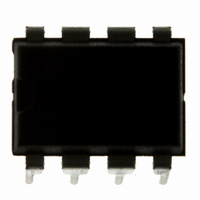
MC9S08QG4MPAE Freescale Semiconductor, MC9S08QG4MPAE Datasheet - Page 120

MC9S08QG4MPAE
Manufacturer Part Number
MC9S08QG4MPAE
Description
IC MCU 4K FLASH 8-PDIP
Manufacturer
Freescale Semiconductor
Series
HCS08r
Datasheet
1.MC9S08QG8CDTER.pdf
(314 pages)
Specifications of MC9S08QG4MPAE
Core Processor
HCS08
Core Size
8-Bit
Speed
20MHz
Connectivity
I²C, SCI, SPI
Peripherals
LVD, POR, PWM, WDT
Number Of I /o
4
Program Memory Size
4KB (4K x 8)
Program Memory Type
FLASH
Ram Size
256 x 8
Voltage - Supply (vcc/vdd)
1.8 V ~ 3.6 V
Data Converters
A/D 4x10b
Oscillator Type
Internal
Operating Temperature
-40°C ~ 125°C
Package / Case
8-DIP (0.300", 7.62mm)
Controller Family/series
HCS08
No. Of I/o's
6
Ram Memory Size
256Byte
Cpu Speed
20MHz
No. Of Timers
2
Embedded Interface Type
I2C, SCI, SPI
Rohs Compliant
Yes
Processor Series
S08QG
Core
HCS08
Data Bus Width
8 bit
Data Ram Size
256 B
Interface Type
I2C, SCI, SPI
Maximum Clock Frequency
20 MHz
Number Of Programmable I/os
12
Number Of Timers
1
Maximum Operating Temperature
+ 125 C
Mounting Style
Through Hole
3rd Party Development Tools
EWS08
Development Tools By Supplier
DEMO9S08QG8E
Minimum Operating Temperature
- 40 C
On-chip Adc
10 bit, 8 Channel
Lead Free Status / RoHS Status
Lead free / RoHS Compliant
Eeprom Size
-
Lead Free Status / Rohs Status
Details
- Current page: 120 of 314
- Download datasheet (6Mb)
Chapter 9 Analog-to-Digital Converter (S08ADC10V1)
9.1.1.3
The ADC is capable of performing conversions using the MCU bus clock, the bus clock divided by two,
or the local asynchronous clock (ADACK) within the module. The alternate clock, ALTCLK, input for the
MC9S08QG8/4 MCU devices is not implemented.
9.1.1.4
The ADC hardware trigger, ADHWT, is output from the real-time interrupt (RTI) counter. The RTI counter
can be clocked by either ICSERCLK or a nominal 1-kHz clock source within the RTI block.
The period of the RTI is determined by the input clock frequency and the RTIS bits. The RTI counter is a
free running counter that generates an overflow at the RTI rate determined by the RTIS bits. When the
ADC hardware trigger is enabled, a conversion is initiated upon an RTI counter overflow.
The RTI can be configured to cause a hardware trigger in MCU run, wait, and stop3.
9.1.1.5
The ADC on MC9S08QG8 devices contains only one analog pin enable register, APCTL1.
9.1.1.6
The ADC module includes a temperature sensor whose output is connected to one of the ADC analog
channel inputs.
where:
For temperature calculations, use the V
in
In application code, the user reads the temperature sensor channel, calculates V
V
less than V
9.1.1.7
The ADC is capable of running in stop3 mode but requires LVDSE and LVDE in SPMSC1 to be set.
118
TEMP25
Appendix A, “Electrical
— V
— V
— m is the hot or cold voltage versus temperature slope in V/°C.
. If V
TEMP25
TEMP
TEMP25
Alternate Clock
Hardware Trigger
Analog Pin Enables
Temperature Sensor
Low-Power Mode Operation
TEMP
Equation 9-1
is the voltage of the temperature sensor channel at the ambient temperature.
the hot slope value is applied in
is greater than V
is the voltage of the temperature sensor channel at 25°C.
Characteristics.”
provides an approximate transfer function of the temperature sensor.
MC9S08QG8 and MC9S08QG4 Data Sheet, Rev. 5
Temp = 25 - ((V
TEMP25
TEMP25
, the cold slope value is applied in
TEMP
and m values from
-V
Equation
TEMP25
) ÷ m)
9-1.
Section A.10, “ADC
Equation
TEMP
Freescale Semiconductor
, and compares to
Characteristics,”
9-1. If V
Eqn. 9-1
TEMP
is
Related parts for MC9S08QG4MPAE
Image
Part Number
Description
Manufacturer
Datasheet
Request
R
Part Number:
Description:
Manufacturer:
Freescale Semiconductor, Inc
Datasheet:
Part Number:
Description:
Manufacturer:
Freescale Semiconductor, Inc
Datasheet:
Part Number:
Description:
Manufacturer:
Freescale Semiconductor, Inc
Datasheet:
Part Number:
Description:
Manufacturer:
Freescale Semiconductor, Inc
Datasheet:
Part Number:
Description:
Manufacturer:
Freescale Semiconductor, Inc
Datasheet:
Part Number:
Description:
Manufacturer:
Freescale Semiconductor, Inc
Datasheet:
Part Number:
Description:
Manufacturer:
Freescale Semiconductor, Inc
Datasheet:
Part Number:
Description:
Manufacturer:
Freescale Semiconductor, Inc
Datasheet:
Part Number:
Description:
Manufacturer:
Freescale Semiconductor, Inc
Datasheet:
Part Number:
Description:
Manufacturer:
Freescale Semiconductor, Inc
Datasheet:
Part Number:
Description:
Manufacturer:
Freescale Semiconductor, Inc
Datasheet:
Part Number:
Description:
Manufacturer:
Freescale Semiconductor, Inc
Datasheet:
Part Number:
Description:
Manufacturer:
Freescale Semiconductor, Inc
Datasheet:
Part Number:
Description:
Manufacturer:
Freescale Semiconductor, Inc
Datasheet:
Part Number:
Description:
Manufacturer:
Freescale Semiconductor, Inc
Datasheet:


