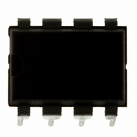
MC9S08QG4MPAE Freescale Semiconductor, MC9S08QG4MPAE Datasheet - Page 165

MC9S08QG4MPAE
Manufacturer Part Number
MC9S08QG4MPAE
Description
IC MCU 4K FLASH 8-PDIP
Manufacturer
Freescale Semiconductor
Series
HCS08r
Datasheet
1.MC9S08QG8CDTER.pdf
(314 pages)
Specifications of MC9S08QG4MPAE
Core Processor
HCS08
Core Size
8-Bit
Speed
20MHz
Connectivity
I²C, SCI, SPI
Peripherals
LVD, POR, PWM, WDT
Number Of I /o
4
Program Memory Size
4KB (4K x 8)
Program Memory Type
FLASH
Ram Size
256 x 8
Voltage - Supply (vcc/vdd)
1.8 V ~ 3.6 V
Data Converters
A/D 4x10b
Oscillator Type
Internal
Operating Temperature
-40°C ~ 125°C
Package / Case
8-DIP (0.300", 7.62mm)
Controller Family/series
HCS08
No. Of I/o's
6
Ram Memory Size
256Byte
Cpu Speed
20MHz
No. Of Timers
2
Embedded Interface Type
I2C, SCI, SPI
Rohs Compliant
Yes
Processor Series
S08QG
Core
HCS08
Data Bus Width
8 bit
Data Ram Size
256 B
Interface Type
I2C, SCI, SPI
Maximum Clock Frequency
20 MHz
Number Of Programmable I/os
12
Number Of Timers
1
Maximum Operating Temperature
+ 125 C
Mounting Style
Through Hole
3rd Party Development Tools
EWS08
Development Tools By Supplier
DEMO9S08QG8E
Minimum Operating Temperature
- 40 C
On-chip Adc
10 bit, 8 Channel
Lead Free Status / RoHS Status
Lead free / RoHS Compliant
Eeprom Size
-
Lead Free Status / Rohs Status
Details
- Current page: 165 of 314
- Download datasheet (6Mb)
11.3.4
Freescale Semiconductor
Reset
BUSY
ARBL
RXAK
Field
IAAS
SRW
IICIF
TCF
7
6
5
4
2
1
0
W
R
IIC Status Register (IICS)
TCF
Transfer Complete Flag — This bit is set on the completion of a byte transfer. Note that this bit is only valid
during or immediately following a transfer to the IIC module or from the IIC module.The TCF bit is cleared by
reading the IICD register in receive mode or writing to the IICD in transmit mode.
0 Transfer in progress.
1 Transfer complete.
Addressed as a Slave — The IAAS bit is set when the calling address matches the programmed slave address.
Writing the IICC register clears this bit.
0 Not addressed.
1 Addressed as a slave.
Bus Busy — The BUSY bit indicates the status of the bus regardless of slave or master mode. The BUSY bit is
set when a START signal is detected and cleared when a STOP signal is detected.
0 Bus is idle.
1 Bus is busy.
Arbitration Lost — This bit is set by hardware when the arbitration procedure is lost. The ARBL bit must be
cleared by software, by writing a one to it.
0 Standard bus operation.
1 Loss of arbitration.
Slave Read/Write — When addressed as a slave the SRW bit indicates the value of the R/W command bit of
the calling address sent to the master.
0 Slave receive, master writing to slave.
1 Slave transmit, master reading from slave.
IIC Interrupt Flag — The IICIF bit is set when an interrupt is pending. This bit must be cleared by software, by
writing a one to it in the interrupt routine. One of the following events can set the IICIF bit:
0 No interrupt pending.
1 Interrupt pending.
Receive Acknowledge — When the RXAK bit is low, it indicates an acknowledge signal has been received after
the completion of one byte of data transmission on the bus. If the RXAK bit is high it means that no acknowledge
signal is detected.
0 Acknowledge received.
1 No acknowledge received.
1
7
• One byte transfer completes
• Match of slave address to calling address
• Arbitration lost
= Unimplemented or Reserved
IAAS
0
6
MC9S08QG8 and MC9S08QG4 Data Sheet, Rev. 5
Table 11-6. IICS Register Field Descriptions
Figure 11-6. IIC Status Register (IICS)
BUSY
0
5
ARBL
0
4
Description
3
0
0
SRW
0
2
Inter-Integrated Circuit (S08IICV1)
IICIF
0
1
RXAK
0
0
163
Related parts for MC9S08QG4MPAE
Image
Part Number
Description
Manufacturer
Datasheet
Request
R
Part Number:
Description:
Manufacturer:
Freescale Semiconductor, Inc
Datasheet:
Part Number:
Description:
Manufacturer:
Freescale Semiconductor, Inc
Datasheet:
Part Number:
Description:
Manufacturer:
Freescale Semiconductor, Inc
Datasheet:
Part Number:
Description:
Manufacturer:
Freescale Semiconductor, Inc
Datasheet:
Part Number:
Description:
Manufacturer:
Freescale Semiconductor, Inc
Datasheet:
Part Number:
Description:
Manufacturer:
Freescale Semiconductor, Inc
Datasheet:
Part Number:
Description:
Manufacturer:
Freescale Semiconductor, Inc
Datasheet:
Part Number:
Description:
Manufacturer:
Freescale Semiconductor, Inc
Datasheet:
Part Number:
Description:
Manufacturer:
Freescale Semiconductor, Inc
Datasheet:
Part Number:
Description:
Manufacturer:
Freescale Semiconductor, Inc
Datasheet:
Part Number:
Description:
Manufacturer:
Freescale Semiconductor, Inc
Datasheet:
Part Number:
Description:
Manufacturer:
Freescale Semiconductor, Inc
Datasheet:
Part Number:
Description:
Manufacturer:
Freescale Semiconductor, Inc
Datasheet:
Part Number:
Description:
Manufacturer:
Freescale Semiconductor, Inc
Datasheet:
Part Number:
Description:
Manufacturer:
Freescale Semiconductor, Inc
Datasheet:


