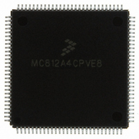
MC812A4CPVE8 Freescale Semiconductor, MC812A4CPVE8 Datasheet - Page 200

MC812A4CPVE8
Manufacturer Part Number
MC812A4CPVE8
Description
IC MCU 16BIT EEPROM 4K 112-LQFP
Manufacturer
Freescale Semiconductor
Series
HC12r
Datasheet
1.MC812A4CPVE8.pdf
(242 pages)
Specifications of MC812A4CPVE8
Core Processor
CPU12
Core Size
16-Bit
Speed
8MHz
Connectivity
SCI, SPI
Peripherals
POR, WDT
Number Of I /o
83
Program Memory Size
4KB (4K x 8)
Program Memory Type
EEPROM
Ram Size
1K x 8
Voltage - Supply (vcc/vdd)
4.5 V ~ 5.5 V
Data Converters
A/D 8x8b
Oscillator Type
Internal
Operating Temperature
-40°C ~ 85°C
Package / Case
112-LQFP
Processor Series
HC812A
Core
HC12
Data Bus Width
16 bit
Data Ram Size
1 KB
Interface Type
SCI, SPI
Maximum Clock Frequency
8 MHz
Number Of Programmable I/os
91
Number Of Timers
8
Maximum Operating Temperature
+ 85 C
Mounting Style
SMD/SMT
Minimum Operating Temperature
- 40 C
On-chip Adc
8 bit, 8 Channel
Controller Family/series
68HC12
No. Of I/o's
91
Eeprom Memory Size
4KB
Ram Memory Size
1KB
Cpu Speed
8MHz
No. Of Timers
1
Rohs Compliant
Yes
Lead Free Status / RoHS Status
Lead free / RoHS Compliant
Eeprom Size
-
Lead Free Status / Rohs Status
Details
Available stocks
Company
Part Number
Manufacturer
Quantity
Price
Company:
Part Number:
MC812A4CPVE8
Manufacturer:
MOTOLOLA
Quantity:
672
Company:
Part Number:
MC812A4CPVE8
Manufacturer:
Freescale Semiconductor
Quantity:
10 000
Part Number:
MC812A4CPVE8
Manufacturer:
NXP/恩智浦
Quantity:
20 000
Company:
Part Number:
MC812A4CPVE80
Manufacturer:
SHARP
Quantity:
5 510
Analog-to-Digital Converter (ATD)
16.6.3 ATD Control Register 2
Read: Anytime
Write: Anytime except ASCIF flag, which is read-only
ADPU — ATD Power-up Bit
AFFC — ATD Fast Flag Clear Bit
AWAI — ATD Stop in Wait Mode Bit
ASCIE — ATD Sequence Complete Interrupt Enable Bit
ASCIF — ATD Sequence Complete Interrupt Flag
200
ADPU enables the clock signal to the ATD and powers up its analog circuits.
When AFFC is set, writing to a result register (ADR0H–ADR7H) clears the associated CCF flag if it is
set. When AFFC is clear, clearing a CCF flag requires a read of the status register followed by a read
of the result register.
ASWAI disables the ATD in wait mode for lower power consumption.
ASCIE enables interrupt requests generated by the ATD sequence complete interrupt flag, ASCIF.
ASCIF is set when a conversion sequence is finished. If the ATD sequence complete interrupt enable
bit, ASCIE, is also set, ASCIF generates an interrupt request.
1 = ATD enabled
0 = ATD disabled
1 = Fast CCF clearing enabled
0 = Fast CCF clearing disabled
1 = ATD disabled in wait mode
0 = ATD enabled in wait mode
1 = ASCIF interrupt requests enabled
0 = ASCIF interrupt requests disabled
1 = Conversion sequence complete
0 = Conversion sequence not complete
Address: $0062
Writing to this register aborts the current conversion sequence.
After ADPU is set, the ATD requires an analog circuit stabilization period.
The ASCIF flag is set only when a conversion sequence is completed and
ASCIE = 1 or interrupts on the analog-to-digital converter (ATD) module
are enabled.
Reset:
Read:
Write:
ADPU
Bit 7
0
Figure 16-5. ATD Control Register 2 (ATDCTL2)
= Unimplemented
AFFC
6
0
MC68HC812A4 Data Sheet, Rev. 7
AWAI
5
0
NOTE
NOTE
NOTE
4
0
0
3
0
0
2
0
0
ASCIE
1
0
Freescale Semiconductor
ASCIF
Bit 0
0


