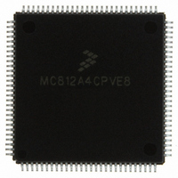
MC812A4CPVE8 Freescale Semiconductor, MC812A4CPVE8 Datasheet - Page 73

MC812A4CPVE8
Manufacturer Part Number
MC812A4CPVE8
Description
IC MCU 16BIT EEPROM 4K 112-LQFP
Manufacturer
Freescale Semiconductor
Series
HC12r
Datasheet
1.MC812A4CPVE8.pdf
(242 pages)
Specifications of MC812A4CPVE8
Core Processor
CPU12
Core Size
16-Bit
Speed
8MHz
Connectivity
SCI, SPI
Peripherals
POR, WDT
Number Of I /o
83
Program Memory Size
4KB (4K x 8)
Program Memory Type
EEPROM
Ram Size
1K x 8
Voltage - Supply (vcc/vdd)
4.5 V ~ 5.5 V
Data Converters
A/D 8x8b
Oscillator Type
Internal
Operating Temperature
-40°C ~ 85°C
Package / Case
112-LQFP
Processor Series
HC812A
Core
HC12
Data Bus Width
16 bit
Data Ram Size
1 KB
Interface Type
SCI, SPI
Maximum Clock Frequency
8 MHz
Number Of Programmable I/os
91
Number Of Timers
8
Maximum Operating Temperature
+ 85 C
Mounting Style
SMD/SMT
Minimum Operating Temperature
- 40 C
On-chip Adc
8 bit, 8 Channel
Controller Family/series
68HC12
No. Of I/o's
91
Eeprom Memory Size
4KB
Ram Memory Size
1KB
Cpu Speed
8MHz
No. Of Timers
1
Rohs Compliant
Yes
Lead Free Status / RoHS Status
Lead free / RoHS Compliant
Eeprom Size
-
Lead Free Status / Rohs Status
Details
Available stocks
Company
Part Number
Manufacturer
Quantity
Price
Company:
Part Number:
MC812A4CPVE8
Manufacturer:
MOTOLOLA
Quantity:
672
Company:
Part Number:
MC812A4CPVE8
Manufacturer:
Freescale Semiconductor
Quantity:
10 000
Part Number:
MC812A4CPVE8
Manufacturer:
NXP/恩智浦
Quantity:
20 000
Company:
Part Number:
MC812A4CPVE80
Manufacturer:
SHARP
Quantity:
5 510
Chapter 7
EEPROM
7.1 Introduction
The MC68HC812A4 EEPROM (electrically erasable, programmable, read-only memory) serves as a
4096-byte nonvolatile memory which can be used for frequently accessed static data or as fast access
program code. Operating system kernels and standard subroutines would benefit from this feature.
The MC68HC812A4 EEPROM is arranged in a 16-bit configuration. The EEPROM array may be read as
either bytes, aligned words, or misaligned words. Access times are one bus cycle for byte and aligned
word access and two bus cycles for misaligned word operations.
Programming is by byte or aligned word. Attempts to program or erase misaligned words will fail. Only the
lower byte will be latched and programmed or erased. Programming and erasing of the user EEPROM
can be done in all modes.
Each EEPROM byte or aligned word must be erased before programming. The EEPROM module
supports byte, aligned word, row (32 bytes), or bulk erase, all using the internal charge pump. Bulk
erasure of odd and even rows is also possible in test modes; the erased state is $FF. The EEPROM
module has hardware interlocks which protect stored data from corruption by accidentally enabling the
program/erase voltage. Programming voltage is derived from the internal V
supply with an internal
DD
charge pump. The EEPROM has a minimum program/erase life of 10,000 cycles over the complete
operating temperature range.
7.2 EEPROM Programmer’s Model
The EEPROM module consists of two separately addressable sections. The first is a 4-byte memory
mapped control register block used for control, testing and configuration of the EEPROM array. The
second section is the EEPROM array itself.
At reset, the 4-byte register section starts at address $00F0 and the EEPROM array is located from
addresses $1000 to $1FFF (see
Figure
7-1). For information on remapping the register block and
EEPROM address space, refer to
Chapter 5 Operating Modes and Resource
Mapping.
Read/write access to the memory array section can be enabled or disabled by the EEON control bit in the
INITEE register. This feature allows the access of memory mapped resources that have lower priority than
the EEPROM memory array. EEPROM control registers can be accessed and EEPROM locations may
be programmed or erased regardless of the state of EEON.
Using the normal EEPROG control, it is possible to continue program/erase operations during wait. For
lowest power consumption during wait, stop program/erase by turning off EEPGM.
If the stop mode is entered during programming or erasing, program/erase voltage is automatically turned
off and the RC clock (if enabled) is stopped. However, the EEPGM control bit remains set. When stop
mode is terminated, the program/erase voltage automatically turns back on if EEPGM is set.
At low bus frequencies, the RC clock must be turned on for program/erase.
MC68HC812A4 Data Sheet, Rev. 7
Freescale Semiconductor
73


