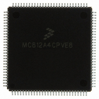
MC812A4CPVE8 Freescale Semiconductor, MC812A4CPVE8 Datasheet - Page 49

MC812A4CPVE8
Manufacturer Part Number
MC812A4CPVE8
Description
IC MCU 16BIT EEPROM 4K 112-LQFP
Manufacturer
Freescale Semiconductor
Series
HC12r
Datasheet
1.MC812A4CPVE8.pdf
(242 pages)
Specifications of MC812A4CPVE8
Core Processor
CPU12
Core Size
16-Bit
Speed
8MHz
Connectivity
SCI, SPI
Peripherals
POR, WDT
Number Of I /o
83
Program Memory Size
4KB (4K x 8)
Program Memory Type
EEPROM
Ram Size
1K x 8
Voltage - Supply (vcc/vdd)
4.5 V ~ 5.5 V
Data Converters
A/D 8x8b
Oscillator Type
Internal
Operating Temperature
-40°C ~ 85°C
Package / Case
112-LQFP
Processor Series
HC812A
Core
HC12
Data Bus Width
16 bit
Data Ram Size
1 KB
Interface Type
SCI, SPI
Maximum Clock Frequency
8 MHz
Number Of Programmable I/os
91
Number Of Timers
8
Maximum Operating Temperature
+ 85 C
Mounting Style
SMD/SMT
Minimum Operating Temperature
- 40 C
On-chip Adc
8 bit, 8 Channel
Controller Family/series
68HC12
No. Of I/o's
91
Eeprom Memory Size
4KB
Ram Memory Size
1KB
Cpu Speed
8MHz
No. Of Timers
1
Rohs Compliant
Yes
Lead Free Status / RoHS Status
Lead free / RoHS Compliant
Eeprom Size
-
Lead Free Status / Rohs Status
Details
Available stocks
Company
Part Number
Manufacturer
Quantity
Price
Company:
Part Number:
MC812A4CPVE8
Manufacturer:
MOTOLOLA
Quantity:
672
Company:
Part Number:
MC812A4CPVE8
Manufacturer:
Freescale Semiconductor
Quantity:
10 000
Part Number:
MC812A4CPVE8
Manufacturer:
NXP/恩智浦
Quantity:
20 000
Company:
Part Number:
MC812A4CPVE80
Manufacturer:
SHARP
Quantity:
5 510
Chapter 4
Resets and Interrupts
4.1 Introduction
Resets and interrupts are exceptions. Each exception has a 16-bit vector that points to the memory
location of the associated exception-handling routine. Vectors are stored in the upper 128 bytes of the
standard 64-Kbyte address map.
The six highest vector addresses are used for resets and non-maskable interrupt sources. The remainder
of the vectors are used for maskable interrupts, and all must be initialized to point to the address of the
appropriate service routine.
4.2 Exception Priority
A hardware priority hierarchy determines which reset or interrupt is serviced first when simultaneous
requests are made. Six sources are not maskable. The remaining sources are maskable and any one of
them can be given priority over other maskable interrupts.
The priorities of the non-maskable sources are:
4.3 Maskable Interrupts
Maskable interrupt sources include on-chip peripheral systems and external interrupt service requests.
Interrupts from these sources are recognized when the global interrupt mask bit (I) in the CCR is cleared.
The default state of the I bit out of reset is 1, but it can be written at any time.
Interrupt sources are prioritized by default but any one maskable interrupt source may be assigned the
highest priority by means of the HPRIO register. The relative priorities of the other sources remain the
same.
An interrupt that is assigned highest priority is still subject to global masking by the I bit in the CCR or by
any associated local bits. Interrupt vectors are not affected by priority assignment. HPRIO can only be
written while the I bit is set (interrupts inhibited).
order of priority.
Freescale Semiconductor
1. POR (power-on reset) or RESET pin
2. Clock monitor reset
3. COP (computer operating properly) watchdog reset
4. Unimplemented instruction trap
5. Software interrupt instruction (SWI)
6. XIRQ signal (if X bit in CCR = 0)
MC68HC812A4 Data Sheet, Rev. 7
Table 4-1
lists interrupt sources and vectors in default
49


