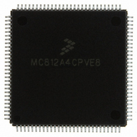
MC812A4CPVE8 Freescale Semiconductor, MC812A4CPVE8 Datasheet - Page 55

MC812A4CPVE8
Manufacturer Part Number
MC812A4CPVE8
Description
IC MCU 16BIT EEPROM 4K 112-LQFP
Manufacturer
Freescale Semiconductor
Series
HC12r
Datasheet
1.MC812A4CPVE8.pdf
(242 pages)
Specifications of MC812A4CPVE8
Core Processor
CPU12
Core Size
16-Bit
Speed
8MHz
Connectivity
SCI, SPI
Peripherals
POR, WDT
Number Of I /o
83
Program Memory Size
4KB (4K x 8)
Program Memory Type
EEPROM
Ram Size
1K x 8
Voltage - Supply (vcc/vdd)
4.5 V ~ 5.5 V
Data Converters
A/D 8x8b
Oscillator Type
Internal
Operating Temperature
-40°C ~ 85°C
Package / Case
112-LQFP
Processor Series
HC812A
Core
HC12
Data Bus Width
16 bit
Data Ram Size
1 KB
Interface Type
SCI, SPI
Maximum Clock Frequency
8 MHz
Number Of Programmable I/os
91
Number Of Timers
8
Maximum Operating Temperature
+ 85 C
Mounting Style
SMD/SMT
Minimum Operating Temperature
- 40 C
On-chip Adc
8 bit, 8 Channel
Controller Family/series
68HC12
No. Of I/o's
91
Eeprom Memory Size
4KB
Ram Memory Size
1KB
Cpu Speed
8MHz
No. Of Timers
1
Rohs Compliant
Yes
Lead Free Status / RoHS Status
Lead free / RoHS Compliant
Eeprom Size
-
Lead Free Status / Rohs Status
Details
Available stocks
Company
Part Number
Manufacturer
Quantity
Price
Company:
Part Number:
MC812A4CPVE8
Manufacturer:
MOTOLOLA
Quantity:
672
Company:
Part Number:
MC812A4CPVE8
Manufacturer:
Freescale Semiconductor
Quantity:
10 000
Part Number:
MC812A4CPVE8
Manufacturer:
NXP/恩智浦
Quantity:
20 000
Company:
Part Number:
MC812A4CPVE80
Manufacturer:
SHARP
Quantity:
5 510
Chapter 5
Operating Modes and Resource Mapping
5.1 Introduction
The MCU can operate in eight different modes. Each mode has a different default memory map and
external bus configuration. After reset, most system resources can be mapped to other addresses by
writing to the appropriate control registers.
5.2 Operating Modes
The states of the BKGD, MODB, and MODA pins during reset determine the operating mode after reset.
The SMODN, MODB, and MODA bits in the MODE register show the current operating mode and provide
limited mode switching during operation. The states of the BKGD, MODB, and MODA pins are latched
into these bits on the rising edge of the reset signal.
The two basic types of operating modes are:
A system development and debug feature, background debug mode (BDM), is available in all modes. In
special single-chip mode, BDM is active immediately after reset.
5.2.1 Normal Operating Modes
These modes provide three operating configurations. Background debugging is available in all three
modes, but must first be enabled for some operations by means of a BDM command. BDM can then be
made active by another BDM command.
Freescale Semiconductor
•
•
Normal modes — Some registers and bits are protected against accidental changes.
Special modes — Protected control registers and bits are allowed greater access for special
purposes such as testing and emulation.
BKGD
1. G.P. = General purpose
0
0
0
0
1
1
1
1
MODB
0
0
1
1
0
0
1
1
MODA
0
1
0
1
0
1
0
1
Reserved (forced to peripheral)
MC68HC812A4 Data Sheet, Rev. 7
Table 5-1. Mode Selection
Special expanded narrow
Normal expanded narrow
Special expanded wide
Normal expanded wide
Special single-chip
Normal single chip
Special peripheral
Mode
G.P.
G.P. I/O
Port A
Port B
ADDR
ADDR
ADDR
ADDR
ADDR
—
(1)
I/O
G.P. I/O
G.P. I/O
Port C
DATA
DATA
DATA
DATA
DATA
—
G.P. I/O
G.P. I/O
G.P. I/O
G.P. I/O
Port D
DATA
DATA
DATA
—
55


