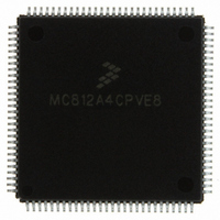
MC812A4CPVE8 Freescale Semiconductor, MC812A4CPVE8 Datasheet - Page 208

MC812A4CPVE8
Manufacturer Part Number
MC812A4CPVE8
Description
IC MCU 16BIT EEPROM 4K 112-LQFP
Manufacturer
Freescale Semiconductor
Series
HC12r
Datasheet
1.MC812A4CPVE8.pdf
(242 pages)
Specifications of MC812A4CPVE8
Core Processor
CPU12
Core Size
16-Bit
Speed
8MHz
Connectivity
SCI, SPI
Peripherals
POR, WDT
Number Of I /o
83
Program Memory Size
4KB (4K x 8)
Program Memory Type
EEPROM
Ram Size
1K x 8
Voltage - Supply (vcc/vdd)
4.5 V ~ 5.5 V
Data Converters
A/D 8x8b
Oscillator Type
Internal
Operating Temperature
-40°C ~ 85°C
Package / Case
112-LQFP
Processor Series
HC812A
Core
HC12
Data Bus Width
16 bit
Data Ram Size
1 KB
Interface Type
SCI, SPI
Maximum Clock Frequency
8 MHz
Number Of Programmable I/os
91
Number Of Timers
8
Maximum Operating Temperature
+ 85 C
Mounting Style
SMD/SMT
Minimum Operating Temperature
- 40 C
On-chip Adc
8 bit, 8 Channel
Controller Family/series
68HC12
No. Of I/o's
91
Eeprom Memory Size
4KB
Ram Memory Size
1KB
Cpu Speed
8MHz
No. Of Timers
1
Rohs Compliant
Yes
Lead Free Status / RoHS Status
Lead free / RoHS Compliant
Eeprom Size
-
Lead Free Status / Rohs Status
Details
Available stocks
Company
Part Number
Manufacturer
Quantity
Price
Company:
Part Number:
MC812A4CPVE8
Manufacturer:
MOTOLOLA
Quantity:
672
Company:
Part Number:
MC812A4CPVE8
Manufacturer:
Freescale Semiconductor
Quantity:
10 000
Part Number:
MC812A4CPVE8
Manufacturer:
NXP/恩智浦
Quantity:
20 000
Company:
Part Number:
MC812A4CPVE80
Manufacturer:
SHARP
Quantity:
5 510
Analog-to-Digital Converter (ATD)
16.11 Using the ATD to Measure a Potentiometer Signal
This exercise allows the student to utilize the ATD on the HC12 to measure a potentiometer signal output
routed from the UDLP1 board to the HC12 ATD pin PAD6. First the ATDCTL registers are initialized. A
delay loop of 100 µs is then executed. The resolution is set up followed by a conversion set up on
channel 6. After waiting for the status bit to set, the result goes to the D accumulator. If the program is
working properly, a different value should be found in the D accumulator as the left potentiometer is varied
for each execution of the program.
16.11.1 Equipment
For this exercise, use the M68HC812A4EVB emulation board.
16.11.2 Code Listing
; ----------------------------------------------------------------------
;
; ----------------------------------------------------------------------
;
MAIN:
DONE:
; ----------------------------------------------
;
; ----------------------------------------------
INIT:
208
ORG
BSR
BSR
BRA
LDAA
STAA
BSR
LDAA
STAA
LDAA
STAA
RTS
A comment line is delimited by a semicolon. If there is no code before
comment, a semicolon(;) must be placed in the first column to avoid
assembly errors.
MAIN PROGRAM
Subroutine INIT: Initialize ATD
$7000
INIT
CONVERT
DONE
#$80
ATDCTL2
DELAY
#$00
ATDCTL3
#$01
ATDCTL4
MC68HC812A4 Data Sheet, Rev. 7
; 16K On-Board RAM, User code data area,
; Branch to INIT subroutine to Initialize ATD
; Branch to CONVERT Subroutine for conversion
; Branch to Self, Convenient place for breakpoint
; Allow ATD to function normally,
; ATD Flags clear normally & disable interrupts
; Delay (100 uS) for WAIT delay time.
; Select continue conversion in BGND Mode
; Ignore FREEZE in ATDCTL3
; Select Final Sample time = 2 A/D clocks
; Prescaler = Div by 4 (PRS4:0 = 1)
; Return from subroutine
start main program at $7000
NOTE
;
Freescale Semiconductor


