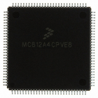
MC812A4CPVE8 Freescale Semiconductor, MC812A4CPVE8 Datasheet - Page 46

MC812A4CPVE8
Manufacturer Part Number
MC812A4CPVE8
Description
IC MCU 16BIT EEPROM 4K 112-LQFP
Manufacturer
Freescale Semiconductor
Series
HC12r
Datasheet
1.MC812A4CPVE8.pdf
(242 pages)
Specifications of MC812A4CPVE8
Core Processor
CPU12
Core Size
16-Bit
Speed
8MHz
Connectivity
SCI, SPI
Peripherals
POR, WDT
Number Of I /o
83
Program Memory Size
4KB (4K x 8)
Program Memory Type
EEPROM
Ram Size
1K x 8
Voltage - Supply (vcc/vdd)
4.5 V ~ 5.5 V
Data Converters
A/D 8x8b
Oscillator Type
Internal
Operating Temperature
-40°C ~ 85°C
Package / Case
112-LQFP
Processor Series
HC812A
Core
HC12
Data Bus Width
16 bit
Data Ram Size
1 KB
Interface Type
SCI, SPI
Maximum Clock Frequency
8 MHz
Number Of Programmable I/os
91
Number Of Timers
8
Maximum Operating Temperature
+ 85 C
Mounting Style
SMD/SMT
Minimum Operating Temperature
- 40 C
On-chip Adc
8 bit, 8 Channel
Controller Family/series
68HC12
No. Of I/o's
91
Eeprom Memory Size
4KB
Ram Memory Size
1KB
Cpu Speed
8MHz
No. Of Timers
1
Rohs Compliant
Yes
Lead Free Status / RoHS Status
Lead free / RoHS Compliant
Eeprom Size
-
Lead Free Status / Rohs Status
Details
Available stocks
Company
Part Number
Manufacturer
Quantity
Price
Company:
Part Number:
MC812A4CPVE8
Manufacturer:
MOTOLOLA
Quantity:
672
Company:
Part Number:
MC812A4CPVE8
Manufacturer:
Freescale Semiconductor
Quantity:
10 000
Part Number:
MC812A4CPVE8
Manufacturer:
NXP/恩智浦
Quantity:
20 000
Company:
Part Number:
MC812A4CPVE80
Manufacturer:
SHARP
Quantity:
5 510
Central Processor Unit (CPU12)
3.3.6 Condition Code Register
S — Stop Disable Bit
X — XIRQ Interrupt Mask Bit
H — Half-Carry Flag
I — Interrupt Mask Bit
N — Negative Flag
Z — Zero Flag
V — Two’s Complement Overflow Flag
C — Carry/Borrow Flag
3.4 Data Types
The CPU12 supports four data types:
A byte is eight bits wide and can be accessed at any byte location. A word is composed of two consecutive
bytes with the most significant byte at the lower value address. There are no special requirements for
alignment of instructions or operands.
46
1. Bit data
2. 8-bit and 16-bit signed and unsigned integers
3. 16-bit unsigned fractions
4. 16-bit addresses
Setting the S bit disables the STOP instruction.
Setting the X bit masks interrupt requests from the XIRQ pin.
The H flag is used only for BCD arithmetic operations. It is set when an ABA, ADD, or ADC instruction
produces a carry from bit 3 of accumulator A. The DAA instruction uses the H flag and the C flag to
adjust the result to correct BCD format.
Setting the I bit disables maskable interrupt sources.
The N flag is set when the result of an operation is less than 0.
The Z flag is set when the result of an operation is all 0s.
The V flag is set when a two’s complement overflow occurs.
The C flag is set when an addition or subtraction operation produces a carry or borrow.
Reset:
U = Unaffected
Bit 7
S
1
Figure 3-9. Condition Code Register (CCR)
X
6
1
MC68HC812A4 Data Sheet, Rev. 7
H
U
5
4
1
I
N
U
3
U
2
Z
V
U
1
Freescale Semiconductor
Bit 0
C
U


